■TOOLS NEEDED — The following list includes rec- ommended tools and devices for working on the heater section of 52C,P units.
Phillips Head Screw Driver
Needle Nose Pliers
Nut Driver
Perform the following steps to remove the Heater
Assembly.
1.DISCONNECT ALL POWER TO UNIT.
2.Remove heater by following instructions in ACCESSING UNIT COMPONENTS section.
After the heater is removed, examine the heater as follows to determine if it is operational:
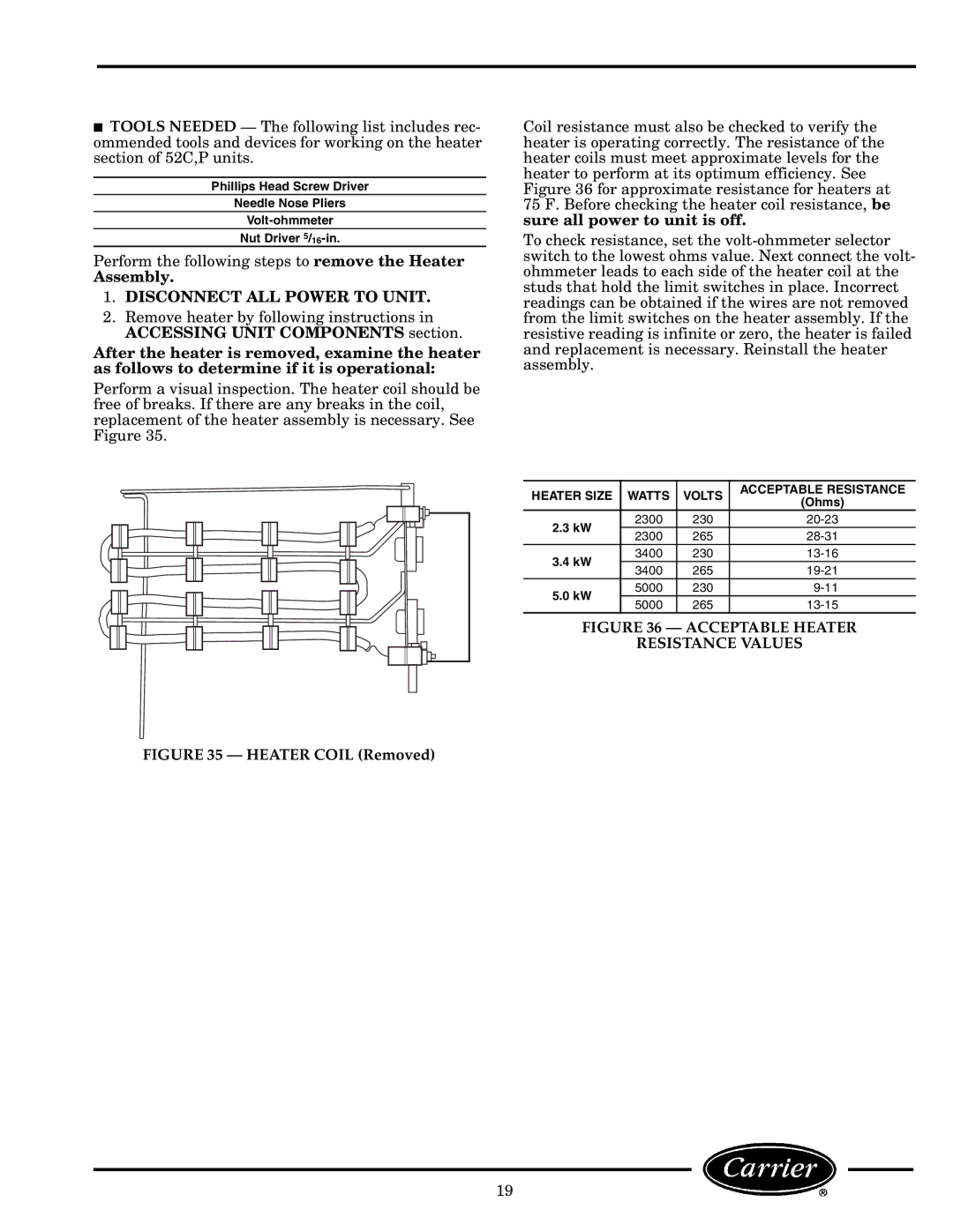
Perform a visual inspection. The heater coil should be free of breaks. If there are any breaks in the coil, replacement of the heater assembly is necessary. See Figure 35.
FIGURE 35 — HEATER COIL (Removed)
Coil resistance must also be checked to verify the heater is operating correctly. The resistance of the heater coils must meet approximate levels for the heater to perform at its optimum efficiency. See Figure 36 for approximate resistance for heaters at 75 F. Before checking the heater coil resistance, be sure all power to unit is off.
To check resistance, set the
HEATER SIZE | WATTS | VOLTS | ACCEPTABLE RESISTANCE | ||
(Ohms) | |||||
|
|
|
| ||
2.3 kW |
| 2300 | 230 | ||
| 2300 | 265 | |||
|
| ||||
3.4 kW |
| 3400 | 230 | ||
| 3400 | 265 | |||
|
| ||||
5.0 kW |
| 5000 | 230 | ||
| 5000 | 265 | |||
|
| ||||
FIGURE 36 — ACCEPTABLE HEATER
RESISTANCE VALUES
19