52C,P
SERIES
|
|
| COMPONENT LEGEND |
|
| |||
|
|
|
|
|
|
|
| |
|
| Component Connection (Marked) | FM | — | Fan Motor | |||
|
| HTR | — | Heater | ||||
|
|
|
| |||||
|
| Component Connection (Unmarked) | IFT | — | Indoor Frost Thermostat | |||
|
|
|
| NEC | — | National Electrical Code | ||
|
| Terminal Board Connection | OL | — | Overload | |||
|
| Field Splice | PCBD | — | Printed Circuit Board | |||
|
| HR1 | — | Heater Relay | ||||
|
| Field Control Wiring | HR2 | — | Heater Relay | |||
|
| CR | — | Compressor Relay | ||||
|
|
|
| |||||
|
| Accessory or Optional Wiring | FR | — | Fan Relay | |||
|
| PLS | — | Primary Limit Switch | ||||
|
|
|
| |||||
|
| To Indicate Common Potential Only | SLS | — | Secondary Limit Switch | |||
|
| SSS | — | Speed Selector Switch | ||||
|
| Not To Represent Wire | ||||||
|
| ST | — | Start Thermistor | ||||
CAP | — | Capacitor | ||||||
TRANS | — | Transformer | ||||||
COMP | — | Compressor |
|
|
|
| ||
NOTES:
1.Recommended for use on grounded power supply only.
2.Compressor and fan motor thermally protected.
3.Use copper conductors only.
4.All wiring must conform with NEC and local codes.
5.Dashed lines indicate components when used.
6.Field control wire suitable for NEC class 2 control circuit, at 24 volts.
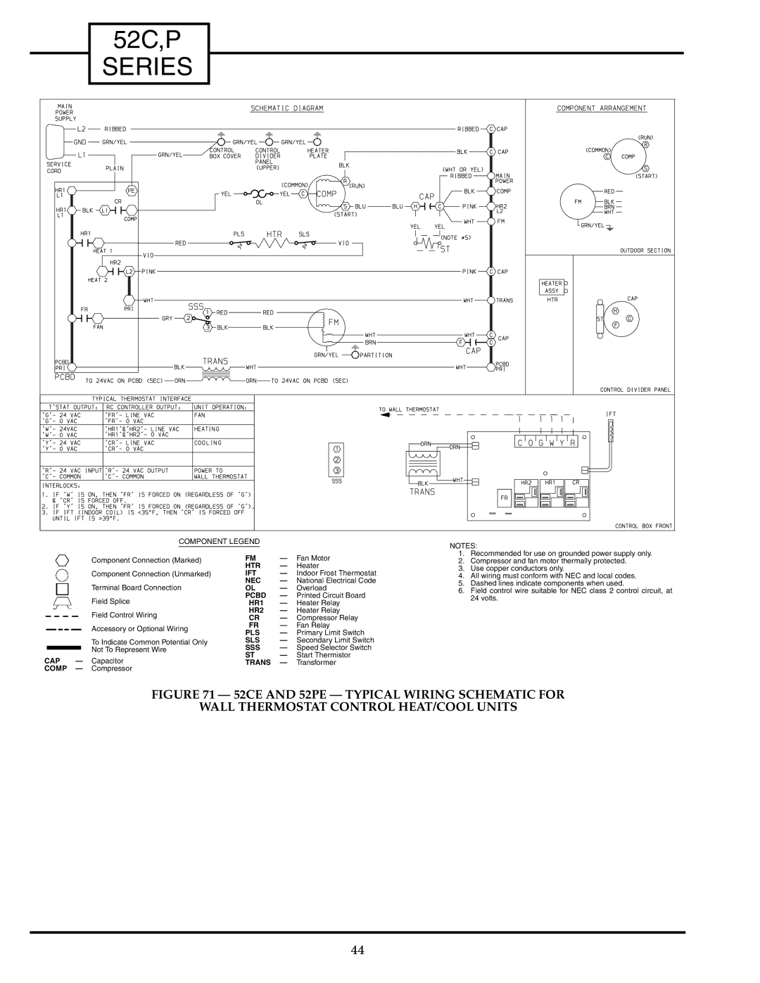
FIGURE 71 — 52CE AND 52PE — TYPICAL WIRING SCHEMATIC FOR
WALL THERMOSTAT CONTROL HEAT/COOL UNITS
44
