COMPONENT LEGEND
|
| Component Connection (Marked) |
|
| Component Connection (Unmarked) |
|
| |
|
| Accessory or Optional Wiring |
|
| |
|
| To Indicate Common Potential Only |
|
| Not To Represent Wire |
CAP | — Capacitor | |
COMP | — Compressor | |
FM | — Fan Motor | |
FCS | — Fan Cycle Switch | |
HTR | — Heater | |
IT | — Indoor Thermostat | |
NEC | — National Electrical Code | |
OL | — Overload | |
PLS | — Primary Limit Switch | |
SLS | — Secondary Limit Switch | |
ST | — Start Thermistor | |
SW | — Switch | |
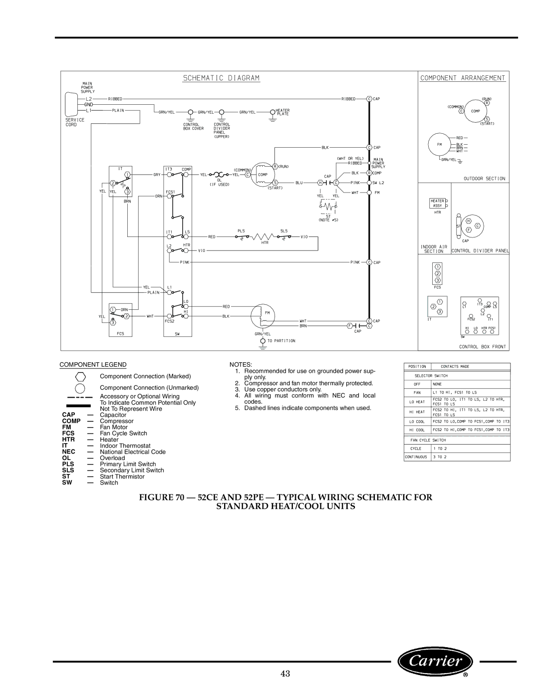
NOTES:
1.Recommended for use on grounded power sup- ply only.
2.Compressor and fan motor thermally protected.
3.Use copper conductors only.
4.All wiring must conform with NEC and local codes.
5.Dashed lines indicate components when used.
FIGURE 70 — 52CE AND 52PE — TYPICAL WIRING SCHEMATIC FOR
STANDARD HEAT/COOL UNITS
43