8.1.1.1 Loopback
Field
Data Access
Direction
Input
None, V.35, T1 #1, T1 #2
None, Equipment Line, Equipment Payload, Equipment TSI, Network
Line, Network Payload, Network TSI
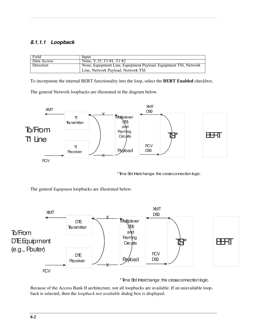
To incorporate the internal BERT functionality into the loop, select the BERT Enabled checkbox. The general Network loopbacks are illustrated in the diagram below.
XMT
To/From T1 Line
RCV
T1
Transmitter
T1
Receiver
X
X
Multiplexer
(TSI)
and
Framing
Circuits
Payload
XMT DS0
RCV DS0
TSI*
BERT
*Time Slot Interchange: the
The general
XMT
To/From
DTE Equipment
(e.g., Router)
RCV
Equipment loopbacks are illustrated below.
DTE | X | Multiplexer |
| ||
Transmitter |
| (TSI) |
|
| and |
|
| Framing |
|
| |
|
| Circuits |
|
|
|
DTE |
| Payload |
Receiver | X | |
|
| |
|
|
|
XMT DS0
RCV DS0
TSI*
BERT
*Time Slot Interchange: the
Because of the Access Bank II architecture, not all loopbacks are available. If an unavailable loop- back is selected, then the loopback not available dialog box is displayed.