|
|
| ESF Framing Format |
|
|
|
|
|
|
| |
|
|
|
|
|
|
|
|
|
|
| |
CI provided loop- | LO | LCF | 0 | 1 | 0 | 1 | 0 | 1 | 0 | 1 | |
start supervision |
|
|
|
|
|
|
|
|
|
| |
|
|
|
|
|
|
|
|
|
| ||
|
|
|
|
|
|
|
|
|
|
|
|
|
| LC | Ringing | 1 | 1 | 1 | 1 | 0 | 0 | 0 | 0 |
DS0 Alarms | DS0 AIS | DS0 AIS | 0 | 0 | 1 | 0 | 0 | 0 | 1 | 0 | |
|
| DS0 yellow | DS0 yellow | 0 | 1 | 1 | 1 | 0 | 1 | 1 | 1 |
The following abbreviations are used in this table: |
|
|
|
|
|
|
|
| |||
LCF | - Loop current feed |
|
|
|
|
|
|
|
|
| |
RLCF - Reverse loop current feed |
|
|
|
|
|
|
|
|
| ||
LCFO - Loop current feed open |
|
|
|
|
|
|
|
|
| ||
LO | - Loop Open |
|
|
|
|
|
|
|
|
|
|
LC | - Loop closure |
|
|
|
|
|
|
|
|
|
|
RG | - Ring ground |
|
|
|
|
|
|
|
|
|
|
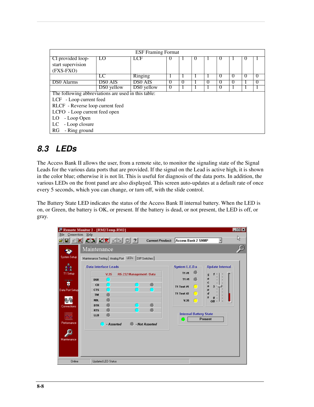
8.3 LEDs
The Access Bank II allows the user, from a remote site, to monitor the signaling state of the Signal Leads for the various data ports that are provided. If the signal on the Lead is active high, it is shown in the color blue; otherwise it is not lit. This is useful for diagnosis of the data ports. In addition, the various LEDs on the front panel are also displayed. This screen
The Battery State LED indicates the status of the Access Bank II internal battery. When the LED is on, or Green, the battery is OK, or present. If the battery is dead, or not present, the LED is off, or gray.