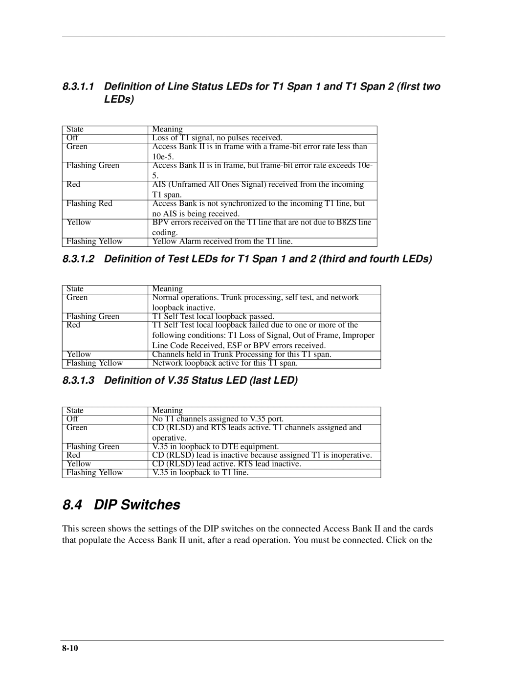
8.3.1.1Definition of Line Status LEDs for T1 Span 1 and T1 Span 2 (first two LEDs)
State | Meaning |
Off | Loss of T1 signal, no pulses received. |
Green | Access Bank II is in frame with a |
| |
Flashing Green | Access Bank II is in frame, but |
| 5. |
|
|
Red | AIS (Unframed All Ones Signal) received from the incoming |
| T1 span. |
Flashing Red | Access Bank is not synchronized to the incoming T1 line, but |
| no AIS is being received. |
Yellow | BPV errors received on the T1 line that are not due to B8ZS line |
| coding. |
|
|
Flashing Yellow | Yellow Alarm received from the T1 line. |
8.3.1.2Definition of Test LEDs for T1 Span 1 and 2 (third and fourth LEDs)
State | Meaning |
Green | Normal operations. Trunk processing, self test, and network |
| loopback inactive. |
|
|
Flashing Green | T1 Self Test local loopback passed. |
Red | T1 Self Test local loopback failed due to one or more of the |
| following conditions: T1 Loss of Signal, Out of Frame, Improper |
| Line Code Received, ESF or BPV errors received. |
Yellow | Channels held in Trunk Processing for this T1 span. |
Flashing Yellow | Network loopback active for this T1 span. |
8.3.1.3Definition of V.35 Status LED (last LED)
State | Meaning |
Off | No T1 channels assigned to V.35 port. |
Green | CD (RLSD) and RTS leads active. T1 channels assigned and |
| operative. |
Flashing Green | V.35 in loopback to DTE equipment. |
Red | CD (RLSD) lead is inactive because assigned T1 is inoperative. |
Yellow | CD (RLSD) lead active. RTS lead inactive. |
Flashing Yellow | V.35 in loopback to T1 line. |
8.4 DIP Switches
This screen shows the settings of the DIP switches on the connected Access Bank II and the cards that populate the Access Bank II unit, after a read operation. You must be connected. Click on the
