Figure 2
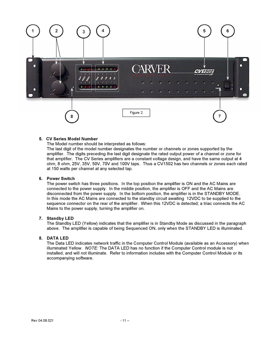
5. CV Series Model Number
The Model number should be interpreted as follows:
The last digit of the model number designates the number or channels or zones supported by the amplifier. The digits preceding the last digit designate the rated output power of a channel or zone for that amplifier. The CV Series amplifiers are a constant voltage design, and have the same output at 4 ohm, 8 ohm, 25V, 35V, 50V, 70V and 100V taps. Thus a CV1502 has two channels or zones each rated at 150 watts per channel at any selected tap.
6.Power Switch
The power switch has three positions. In the top position the amplifier is ON and the AC Mains are connected to the power supply. In the middle position, the amplifier is OFF and the AC Mains are disconnected from the power supply. In the bottom position, the amplifier is in the STANDBY MODE. In this mode the AC Mains are connected to the standby circuit awaiting 12VDC to be supplied to the sequence connector on the rear of the amplifier. When this 12VDC is detected; a triac connects the AC Mains to the power supply, turning the amplifier on.
7.Standby LED
The Standby LED (Yellow) indicates that the amplifier is in Standby Mode as discussed in the paragraph above. The amplifier is capable of being Sequenced ON, only when the STANDBY LED is illuminated.
8.DATA LED
The Data LED indicates network traffic in the Computer Control Module (available as an Accessory) when illuminated Yellow. NOTE: The DATA LED has no function if the Computer Control module is not installed, and will not illuminate. Refer to information includes with the Computer Control Module or its accompanying software.
Rev 04.08.021 | - 11 – |