amplifiers in the sequence are connected. Connect the negative side of the DC supply to the chassis ground terminal. If the amplifiers are mounted together in a rack where a common AC Ground connects the chassis grounds together through common connection via the metal rack rail, no other connections should be required. (See Figure 10) If this is not the case, simply connect all of the “Chassis Ground” terminals together. (See Figure
11)Place the CV amplifiers’ power switches in the Standby (fully down) position.
To remotely begin the sequencing function, close the circuit, and supply the DC voltage to the “RCV” receive pin on the first amplifier and the subsequent amplifiers should turn on at 0.5 second intervals. Please note that the front panel “Power Switch” should be in the “Standby” position on all of the amplifiers in this group. When the DC voltage is interrupted, the amplifiers will then turn OFF. If there are signal processing and input source devices in the system, they should be turned ON before the amplifiers are “sequenced” ON, and these same devices should be powered down after the amplifiers are “sequenced” OFF. This will avoid large transient thumps being passed to the loudspeakers attached to the system.
12VDC Supply
Figure 11
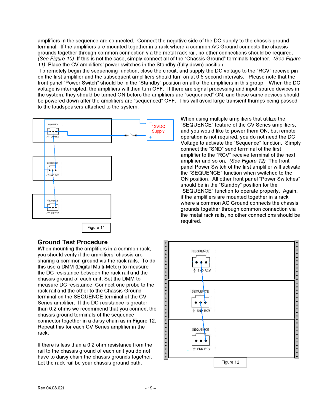
When using multiple amplifiers that utilize the “SEQUENCE” feature of the CV Series amplifiers, and you would like to power them ON, but remote operation is not required, you do not need the DC Voltage to activate the “Sequence” function. Simply connect the “SND” send terminal of the first amplifier to the “RCV” receive terminal of the next amplifier and so on. (See Figure 12) The front panel Power Switch of the first amplifier will activate the “SEQUENCE” function when switched to the ON position. All other front panel “Power Switches” should be in the “Standby” position for the “SEQUENCE” function to operate properly. Again, if the amplifiers are mounted together in a rack where a common AC Ground connects the chassis grounds together through common connection via the metal rack rails, no other connections should be required.
Ground Test Procedure
When mounting the amplifiers in a common rack, you should verify if the amplifiers’ chassis are sharing a common ground via the rack rails. To do this use a DMM (Digital
If there is less than a 0.2 ohm resistance from the |
|
rail to the chassis ground of each unit you do not |
|
have to daisy chain the chassis grounds together. |
|
Let the rack rail be your chassis ground path. | Figure 12 |
Rev 04.08.021 | - 19 – |