4.Remote Level
The Remote Level Connector is used to connect a Remote Level Control to the CV Series amplifier. The connector is a Euro Style connector with the following connection points, from left to right. (See Figure 5)
RTN – Return, CV2 – Control Voltage for Channel 2 on Dual Channel models, CV1 – Control Voltage for Channel 1, and +5V volt send from the VCA package. More information on how to connect this feature is available later in this manual
Figure 5
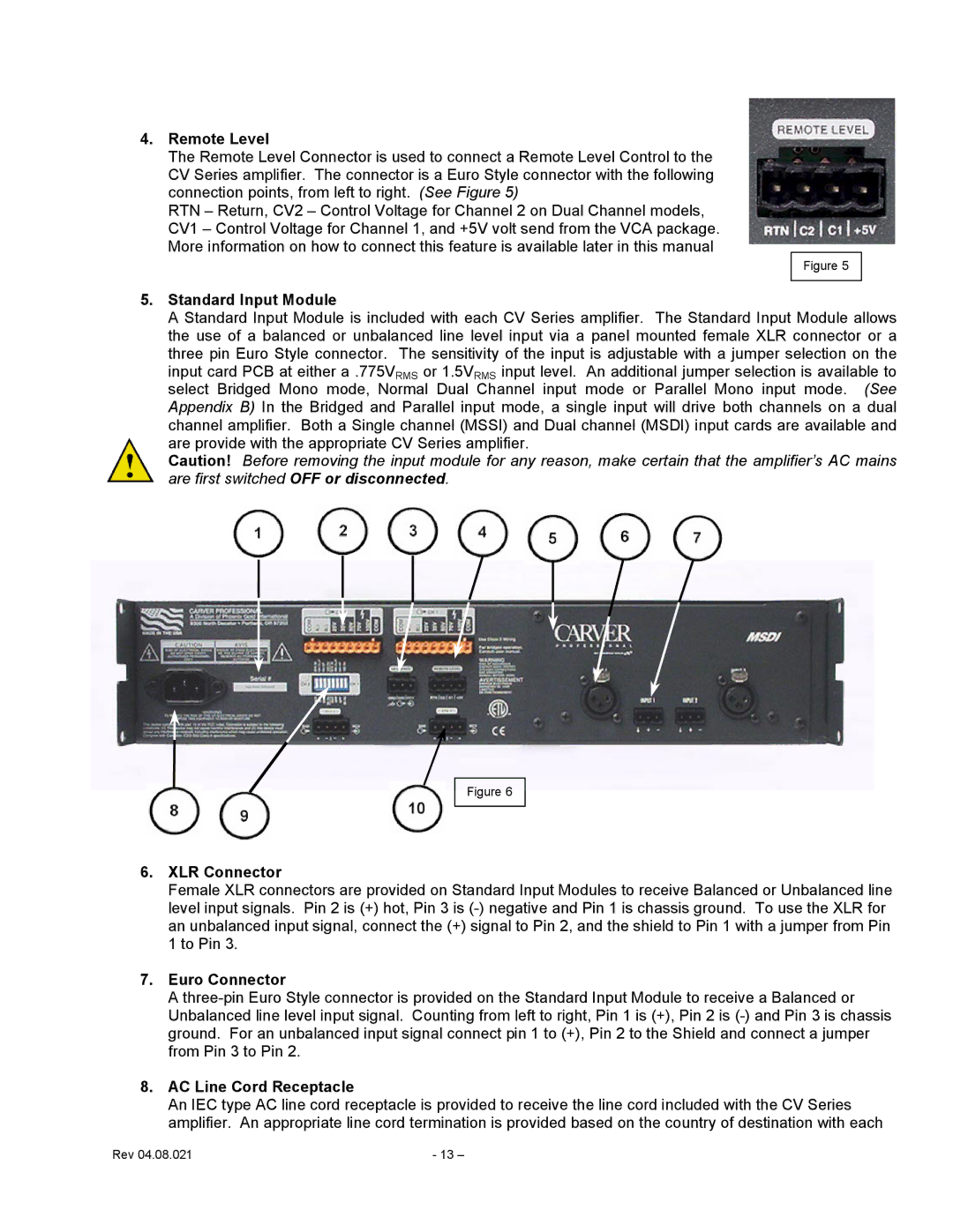
5.Standard Input Module
A Standard Input Module is included with each CV Series amplifier. The Standard Input Module allows the use of a balanced or unbalanced line level input via a panel mounted female XLR connector or a three pin Euro Style connector. The sensitivity of the input is adjustable with a jumper selection on the input card PCB at either a .775VRMS or 1.5VRMS input level. An additional jumper selection is available to select Bridged Mono mode, Normal Dual Channel input mode or Parallel Mono input mode. (See Appendix B) In the Bridged and Parallel input mode, a single input will drive both channels on a dual channel amplifier. Both a Single channel (MSSI) and Dual channel (MSDI) input cards are available and are provide with the appropriate CV Series amplifier.
Caution! Before removing the input module for any reason, make certain that the amplifier’s AC mains are first switched OFF or disconnected.
Figure 6
6.XLR Connector
Female XLR connectors are provided on Standard Input Modules to receive Balanced or Unbalanced line level input signals. Pin 2 is (+) hot, Pin 3 is
7.Euro Connector
A
8.AC Line Cord Receptacle
An IEC type AC line cord receptacle is provided to receive the line cord included with the CV Series amplifier. An appropriate line cord termination is provided based on the country of destination with each
Rev 04.08.021 | - 13 – |