APPENDIX
DMX Primer
There are 512 channels in a
DMX fixtures are designed to receive data through a serial Daisy Chain. A Daisy Chain connection is where the DATA OUT of one fixture connects to the DATA IN of the next fixture. The order in which the fixtures are connected is not important and has no effect on how a controller communicates to each fixture. Use an order that provides for the easiest and most direct cabling. Connect fixtures using shielded two conductor twisted pair cable with three pin XLR male to female connectors. The shield connection is pin 1, while pin 2 is Data Negative
FI XT UR E LI NK ING
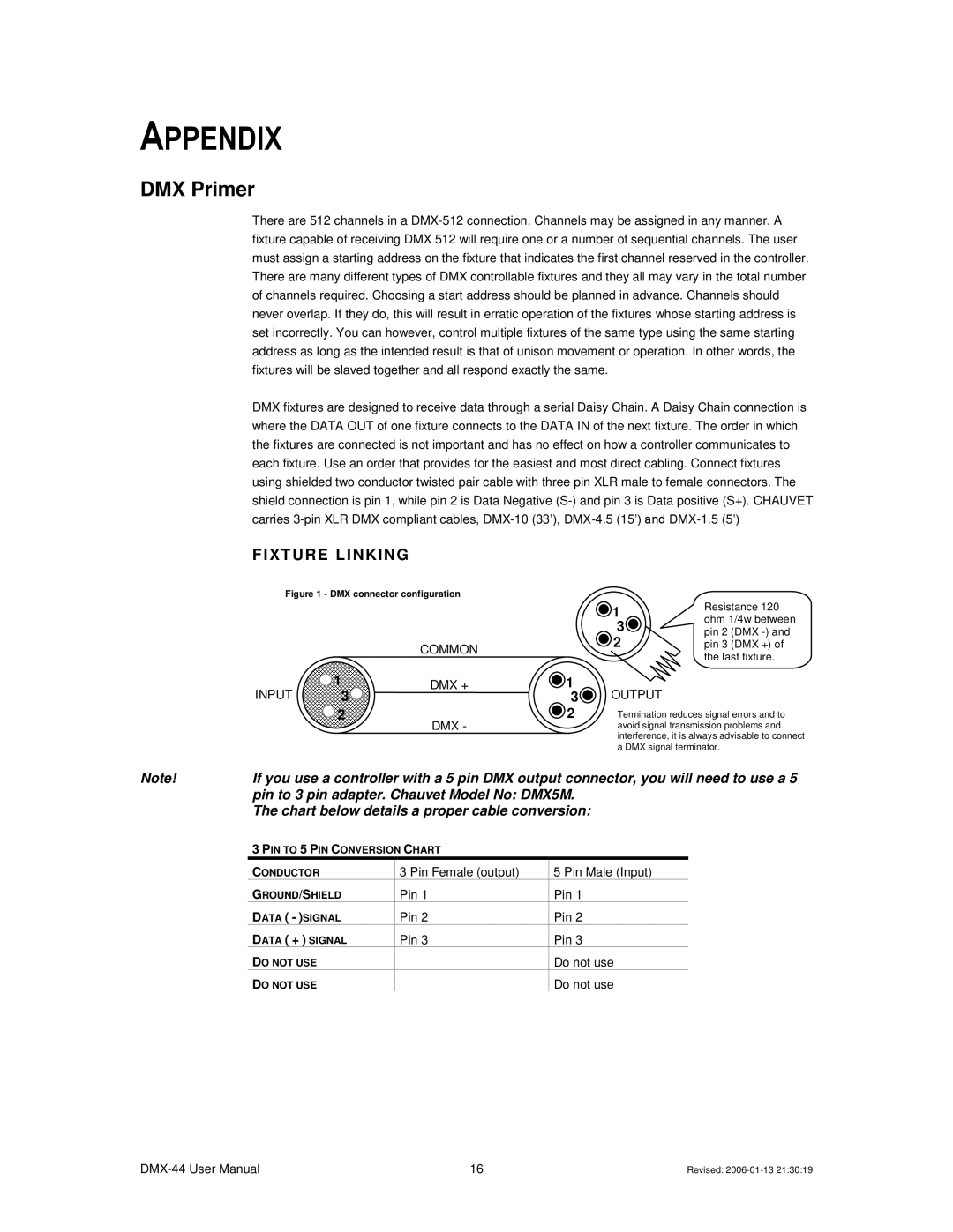
Figure 1 - DMX connector configuration
COMMON
INPUT | 1 | DMX + | |
3 | |||
| |||
| 2 | DMX - | |
|
|
1 | Resistance 120 | |
ohm 1/4w between | ||
3 | ||
pin 2 (DMX | ||
|
2pin 3 (DMX +) of the last fixture.
![]() 1
1
3 | OUTPUT |
2 | Termination reduces signal errors and to |
| avoid signal transmission problems and |
| interference, it is always advisable to connect |
| a DMX signal terminator. |
Note! | If you use a controller with a 5 pin DMX output connector, you will need to use a 5 |
| pin to 3 pin adapter. Chauvet Model No: DMX5M. |
| The chart below details a proper cable conversion: |
3PIN TO 5 PIN CONVERSION CHART
CONDUCTOR
GROUND/SHIELD
DATA ( - )SIGNAL
DATA ( + ) SIGNAL
DO NOT USE
DO NOT USE
3 Pin Female (output)
Pin 1
Pin 2
Pin 3
5 Pin Male (Input)
Pin 1
Pin 2
Pin 3
Do not use
Do not use
16 | Revised: |