Removing and Replacing a Card Cage Assembly
Removing an AC-Input Power Supply
Perform the following steps to remove an
Step 1 Attach an antistatic wrist strap to yourself and to one of the two ESD connection sockets located on the front edges of the upper card cage or to bare metal on the frame.
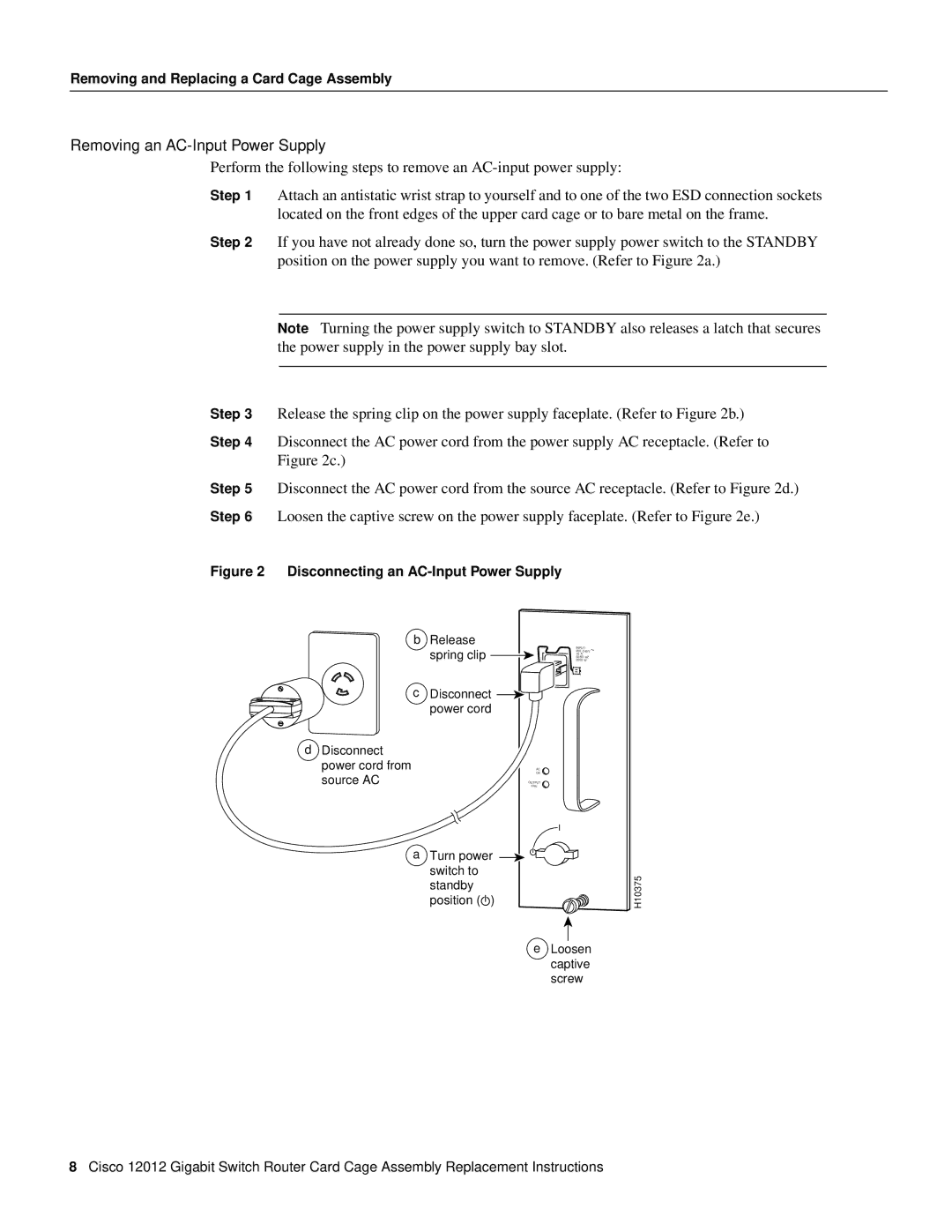
Step 2 If you have not already done so, turn the power supply power switch to the STANDBY position on the power supply you want to remove. (Refer to Figure 2a.)
Note Turning the power supply switch to STANDBY also releases a latch that secures the power supply in the power supply bay slot.
Step 3 Release the spring clip on the power supply faceplate. (Refer to Figure 2b.)
Step 4 Disconnect the AC power cord from the power supply AC receptacle. (Refer to
Figure 2c.)
Step 5 Disconnect the AC power cord from the source AC receptacle. (Refer to Figure 2d.)
Step 6 Loosen the captive screw on the power supply faceplate. (Refer to Figure 2e.)
Figure 2 Disconnecting an AC-Input Power Supply
bRelease
spring clip ![]()
c | Disconnect |
| power cord |
d Disconnect |
|
power cord from | OK |
source AC | AC |
FAIL | |
| OUTPUT |
INPUT:
200 - 240V
10A 50/60 HZ 2000 W
~
aTurn power switch to standby
position (![]() )
)
e Loosen captive screw
H10375
8Cisco 12012 Gigabit Switch Router Card Cage Assembly Replacement Instructions