Removing and Replacing a Card Cage Assembly
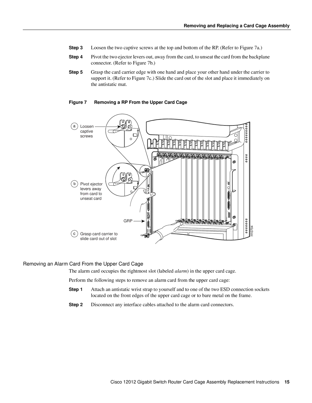
Step 3 Loosen the two captive screws at the top and bottom of the RP. (Refer to Figure 7a.)
Step 4 Pivot the two ejector levers out, away from the card, to unseat the card from the backplane connector. (Refer to Figure 7b.)
Step 5 Grasp the card carrier edge with one hand and place your other hand under the carrier to support it. (Refer to Figure 7c.) Slide the card out of the slot and place it immediately on the antistatic mat.
Figure 7 Removing a RP From the Upper Card Cage
a Loosen captive screws
|
|
|
| 0 |
|
|
b | Pivot ejector |
|
| CRITICAL |
| |
|
| MAJOR |
| |||
|
| MINOR |
| |||
| levers away |
|
| ACO/LT |
| |
|
|
| EJECT |
|
|
|
|
| SLOTSLOT |
|
|
| |
| from card to | AUX | RESET |
|
|
|
|
|
|
|
| ALARM 1 | |
| unseat card |
|
|
|
| |
| CONSOLE |
|
|
|
| |
|
|
|
|
|
| |
|
|
|
|
|
| ALARM 2 |
|
| LINK |
| ENABLEDFAIL |
| |
|
| COLL |
| 0 |
| |
|
| TX |
|
|
| |
|
|
| RX |
| 1 | CSC |
|
|
|
|
| 0 |
|
|
|
|
|
| 1 |
|
|
|
|
| ALARM | 2 | SFC |
|
| MII |
|
| ||
|
| GRP |
|
|
|
|
c | Grasp card carrier to | GIGABITROUTE PROCESSOR |
|
|
| H10704 |
| slide card out of slot |
|
|
|
|
|
Removing an Alarm Card From the Upper Card Cage
The alarm card occupies the rightmost slot (labeled alarm) in the upper card cage.
Perform the following steps to remove an alarm card from the upper card cage:
Step 1 Attach an antistatic wrist strap to yourself and to one of the two ESD connection sockets located on the front edges of the upper card cage or to bare metal on the frame.
Step 2 Disconnect any interface cables attached to the alarm card connectors.
Cisco 12012 Gigabit Switch Router Card Cage Assembly Replacement Instructions 15