1760 specifications
The Cisco Systems 1760 series routers are part of Cisco’s popular line of integrated services routers, designed primarily for small to medium-sized businesses and branch offices. The 1760 series was introduced to provide robust connectivity and routing solutions that facilitate secure and reliable networking. Aimed at offering flexibility, these routers integrate multiple functionalities to enhance operational performance.One of the main features of the Cisco 1760 router is its modularity. It supports various interface and service modules that allow for customization based on specific networking needs. This modular design enables businesses to expand their networking capabilities over time without necessitating a complete hardware overhaul. The router typically comes equipped with two WAN slots and numerous interface options, including Fast Ethernet and serial interfaces.
The 1760 series routers also support advanced security features, providing businesses with a secure environment for their data transmissions. Built-in firewall capabilities, along with support for Virtual Private Network (VPN) protocols, ensure that sensitive information remains protected. Furthermore, the integration of IPsec and MPLS security features assists organizations in maintaining secure and scalable connections across diverse networks.
Another characteristic of the Cisco 1760 is its support for various technologies, including Quality of Service (QoS). QoS functionality allows network administrators to prioritize traffic, ensuring that critical applications receive the bandwidth they require while minimizing latency. This ability is particularly valuable in environments where voice, video, and essential data applications compete for resources.
The router’s ease of management is also noteworthy. With Cisco’s IOS (Internetwork Operating System), the 1760 provides a user-friendly interface allowing for straightforward configuration and monitoring. The simplicity in managing the network devices helps reduce the burden on IT personnel and enhances overall operational efficiency.
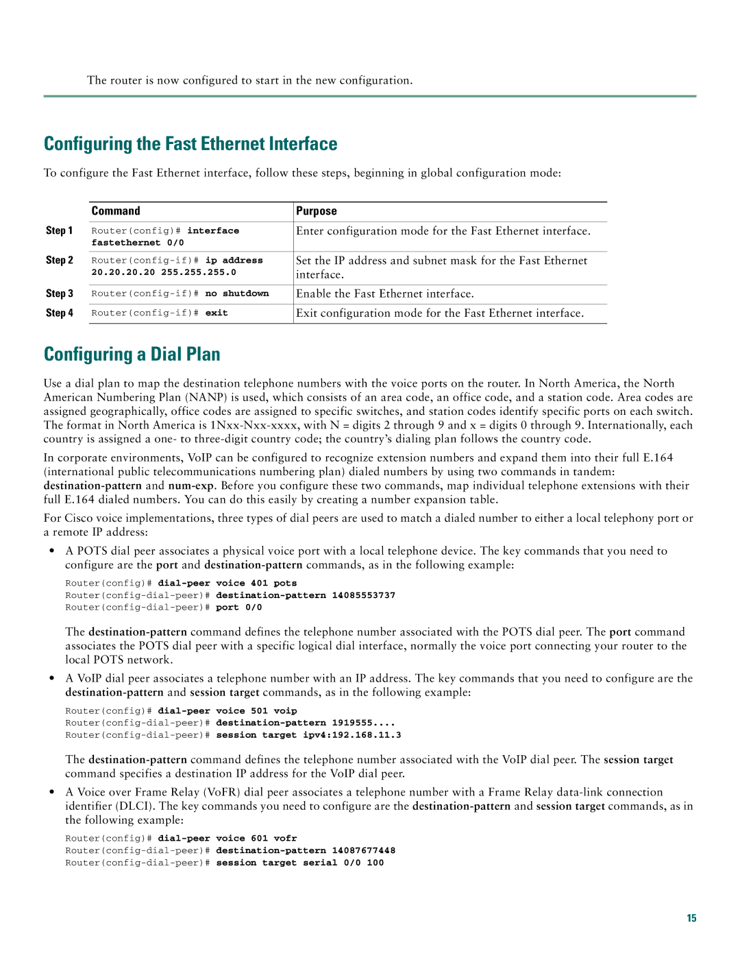
Further enhancing the router’s capabilities is its support for voice over IP (VoIP) applications, making it an ideal choice for organizations looking to implement modern telephony solutions. The ability to support multiple voice channels while maintaining adequate data throughput positions the 1760 as an attractive option for businesses transitioning to unified communications.
In summary, the Cisco Systems 1760 series routers exhibit a harmonious blend of modularity, robust security, traffic management, and VoIP support. They effectively meet the demands of modern networking environments, making them a reliable choice for organizations aiming to streamline operations while ensuring secure connectivity. With their adaptable design, these routers can serve as a powerful backbone for enterprise networking needs.
