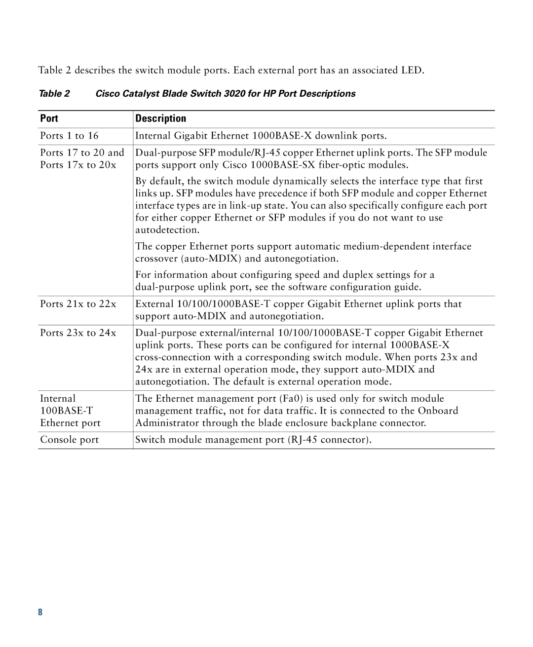
Table 2 describes the switch module ports. Each external port has an associated LED.
Table 2 Cisco Catalyst Blade Switch 3020 for HP Port Descriptions
Port | Description |
|
|
Ports 1 to 16 | Internal Gigabit Ethernet |
|
|
Ports 17 to 20 and | |
Ports 17x to 20x | ports support only Cisco |
| By default, the switch module dynamically selects the interface type that first |
| links up. SFP modules have precedence if both SFP module and copper Ethernet |
| interface types are in |
| for either copper Ethernet or SFP modules if you do not want to use |
| autodetection. |
| The copper Ethernet ports support automatic |
| crossover |
| For information about configuring speed and duplex settings for a |
| |
|
|
Ports 21x to 22x | External |
| support |
|
|
Ports 23x to 24x | |
| uplink ports. These ports can be configured for internal |
| |
| 24x are in external operation mode, they support |
| autonegotiation. The default is external operation mode. |
|
|
Internal | The Ethernet management port (Fa0) is used only for switch module |
| management traffic, not for data traffic. It is connected to the Onboard |
Ethernet port | Administrator through the blade enclosure backplane connector. |
|
|
Console port | Switch module management port |
|
|
8