Chapter 3 Installing the Cisco Global Site Selector 4490
Installing Your Unit
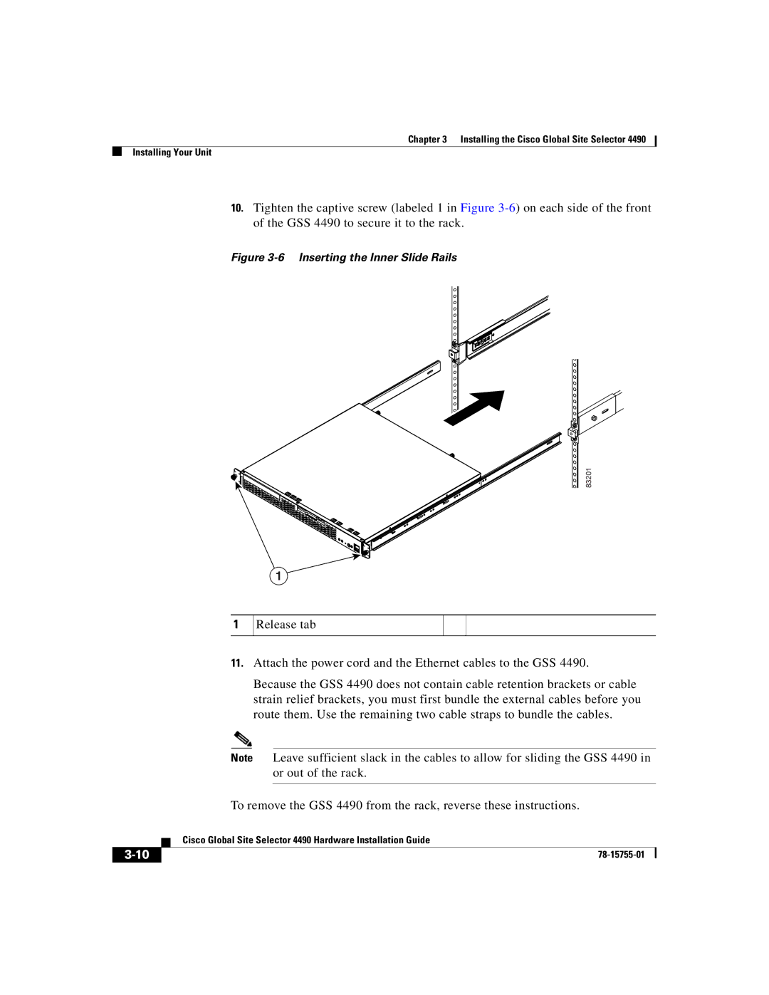
10.Tighten the captive screw (labeled 1 in Figure
Figure 3-6 Inserting the Inner Slide Rails
83201
1
1
Release tab
11.Attach the power cord and the Ethernet cables to the GSS 4490.
Because the GSS 4490 does not contain cable retention brackets or cable strain relief brackets, you must first bundle the external cables before you route them. Use the remaining two cable straps to bundle the cables.
Note Leave sufficient slack in the cables to allow for sliding the GSS 4490 in or out of the rack.
To remove the GSS 4490 from the rack, reverse these instructions.
| Cisco Global Site Selector 4490 Hardware Installation Guide |