Hardware Description 1 |
Connections to POTS Splitters or Telephone Lines
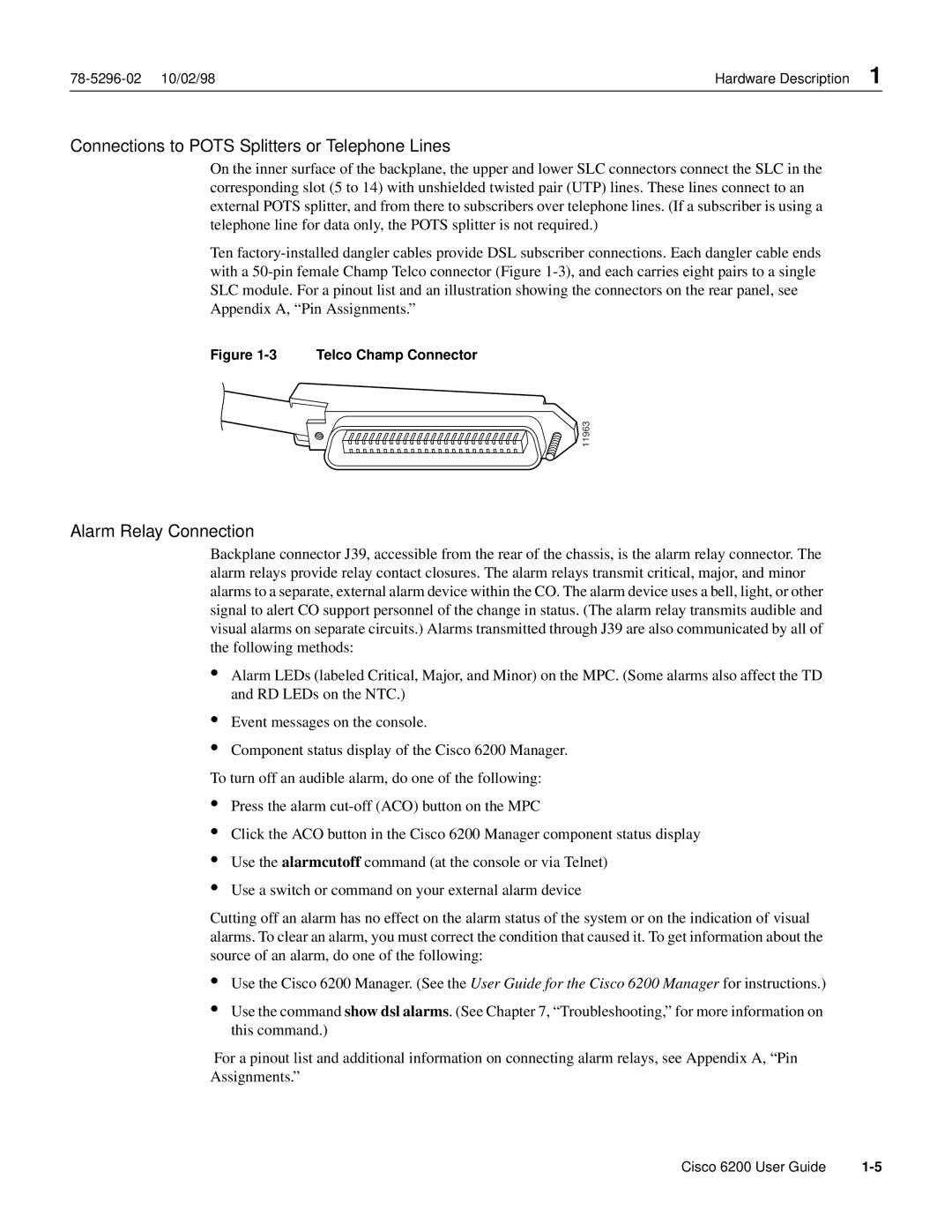
On the inner surface of the backplane, the upper and lower SLC connectors connect the SLC in the corresponding slot (5 to 14) with unshielded twisted pair (UTP) lines. These lines connect to an external POTS splitter, and from there to subscribers over telephone lines. (If a subscriber is using a telephone line for data only, the POTS splitter is not required.)
Ten
Figure 1-3 Telco Champ Connector
![]() 11963
11963
Alarm Relay Connection
Backplane connector J39, accessible from the rear of the chassis, is the alarm relay connector. The alarm relays provide relay contact closures. The alarm relays transmit critical, major, and minor alarms to a separate, external alarm device within the CO. The alarm device uses a bell, light, or other signal to alert CO support personnel of the change in status. (The alarm relay transmits audible and visual alarms on separate circuits.) Alarms transmitted through J39 are also communicated by all of the following methods:
•Alarm LEDs (labeled Critical, Major, and Minor) on the MPC. (Some alarms also affect the TD and RD LEDs on the NTC.)
•
•
Event messages on the console.
Component status display of the Cisco 6200 Manager.
To turn off an audible alarm, do one of the following:
•
•
•
•
Press the alarm
Click the ACO button in the Cisco 6200 Manager component status display
Use the alarmcutoff command (at the console or via Telnet)
Use a switch or command on your external alarm device
Cutting off an alarm has no effect on the alarm status of the system or on the indication of visual alarms. To clear an alarm, you must correct the condition that caused it. To get information about the source of an alarm, do one of the following:
•Use the Cisco 6200 Manager. (See the User Guide for the Cisco 6200 Manager for instructions.)
•Use the command show dsl alarms. (See Chapter 7, “Troubleshooting,” for more information on this command.)
For a pinout list and additional information on connecting alarm relays, see Appendix A, “Pin Assignments.”
Cisco 6200 User Guide |