Chapter 24 Configuring ATM Router Module Interfaces
Configuring Classical IP over ATM in an SVC Environment
NSAP Address Example
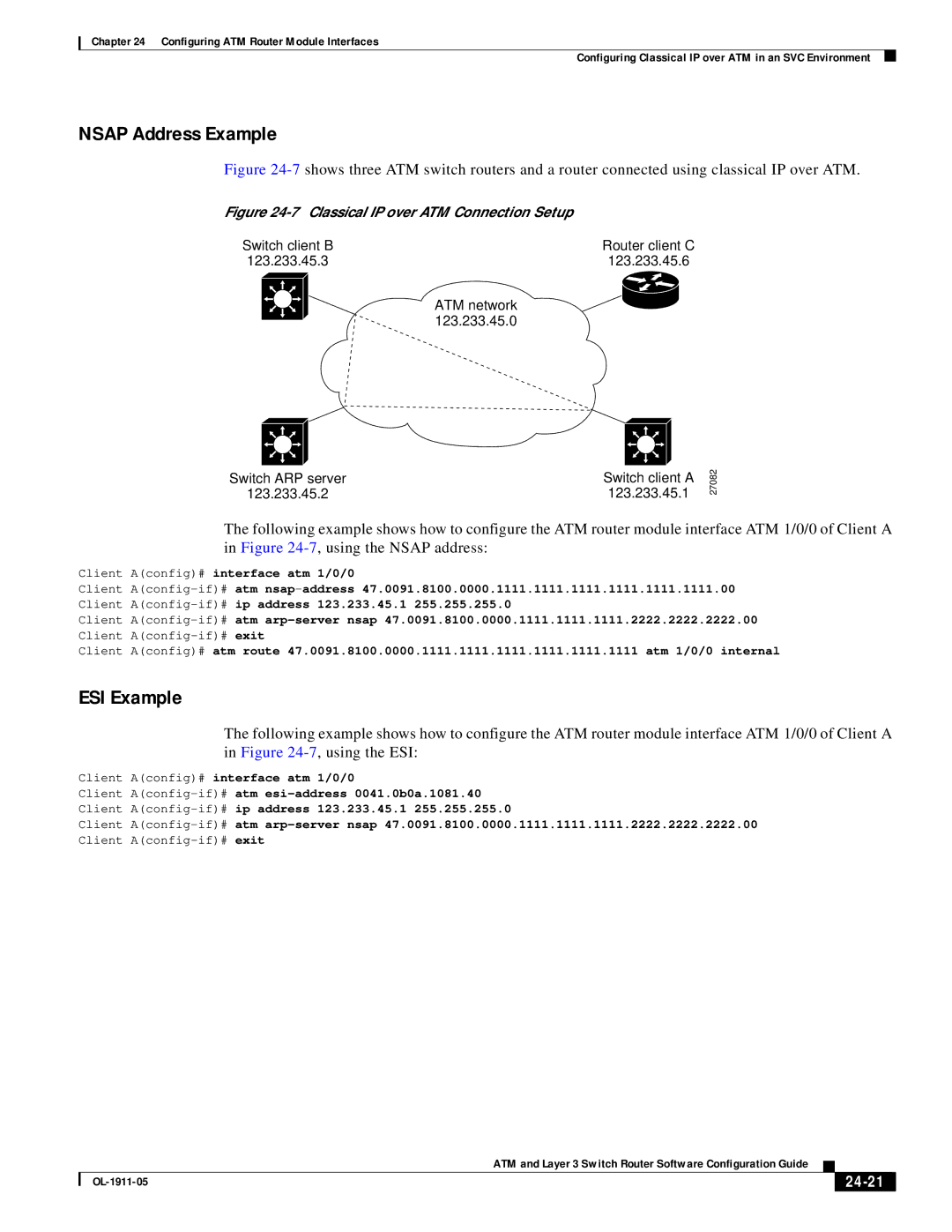
Figure 24-7 shows three ATM switch routers and a router connected using classical IP over ATM.
Figure |
|
Switch client B | Router client C |
123.233.45.3 | 123.233.45.6 |
ATM network |
|
123.233.45.0 |
|
Switch ARP server | Switch client A |
123.233.45.2 | 123.233.45.1 |
27082
The following example shows how to configure the ATM router module interface ATM 1/0/0 of Client A in Figure
Client A(config)# interface atm 1/0/0
Client
Client
Client A(config)# atm route 47.0091.8100.0000.1111.1111.1111.1111.1111.1111 atm 1/0/0 internal
ESI Example
The following example shows how to configure the ATM router module interface ATM 1/0/0 of Client A in Figure
Client A(config)# interface atm 1/0/0
Client
Client
|
| ATM and Layer 3 Switch Router Software Configuration Guide |
|
| ||
|
|
| ||||
|
|
|
|
| ||
|
|
|
| |||
