2Install the PIX 515E
DMZ server Switch | PIX 515E |
|
DMZ |
|
|
Switch | Inside |
|
| Outside | Power |
|
| |
|
| cable |
Laptop | Router |
|
|
| |
computer |
|
|
| Internet |
|
Printer |
|
|
Personal |
|
|
computer |
|
|
97998
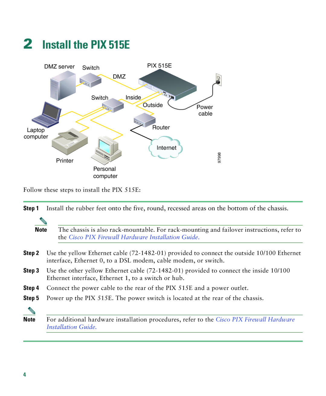
Follow these steps to install the PIX 515E:
Step 1 Install the rubber feet onto the five, round, recessed areas on the bottom of the chassis.
Note The chassis is also
Step 2 Use the yellow Ethernet cable
Step 3 Use the other yellow Ethernet cable
Step 4 Connect the power cable to the rear of the PIX 515E and a power outlet.
Step 5 Power up the PIX 515E. The power switch is located at the rear of the chassis.
Note For additional hardware installation procedures, refer to the Cisco PIX Firewall Hardware Installation Guide.
4
