Chapter 1 Product Overview
Functional Overview
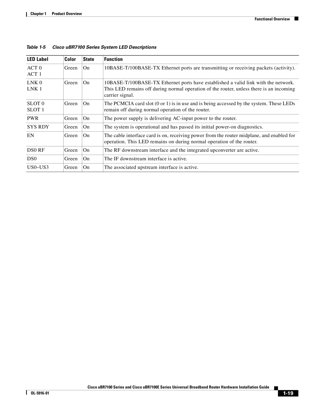
Table
LED Label | Color | State | Function |
|
|
|
|
ACT 0 | Green | On | |
ACT 1 |
|
|
|
|
|
|
|
LNK 0 | Green | On | |
LNK 1 |
|
| This LED remains off during normal operation of the router, unless there is an incoming |
|
|
| carrier signal. |
|
|
|
|
SLOT 0 | Green | On | The PCMCIA card slot (0 or 1) is in use and is being accessed by the system. These LEDs |
SLOT 1 |
|
| remain off during normal operation of the router. |
|
|
|
|
PWR | Green | On | The power supply is delivering |
|
|
|
|
SYS RDY | Green | On | The system is operational and has passed its initial |
|
|
|
|
EN | Green | On | The cable interface card is on, receiving power from the router midplane, and enabled for |
|
|
| operation. This LED remains on during normal operation of the router. |
|
|
|
|
DS0 RF | Green | On | The RF downstream interface and the integrated upconverter are active. |
|
|
|
|
DS0 | Green | On | The IF downstream interface is active. |
|
|
|
|
| Green | On | The associated upstream interface is active. |
|
|
|
|
Cisco uBR7100 Series and Cisco uBR7100E Series Universal Broadband Router Hardware Installation Guide
|
| ||
|
|