Connecting a Cable to the
Connecting a Cable to the
Caution If the symbol of suitability with an overlaid cross
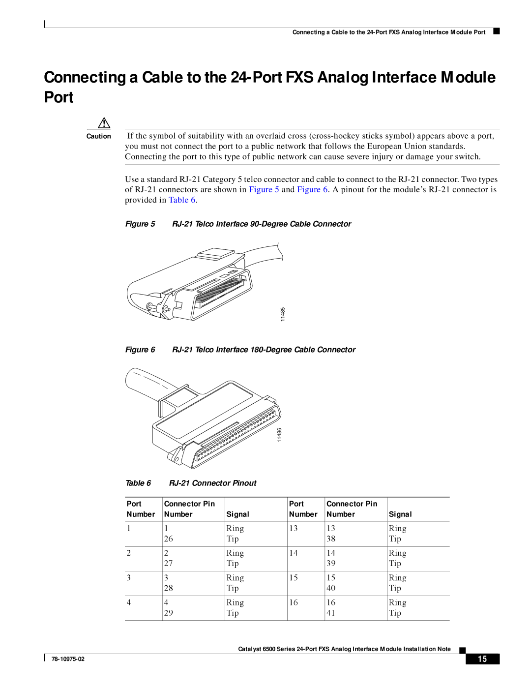
Use a standard
Figure 5 RJ-21 Telco Interface 90-Degree Cable Connector
11485
Figure 6 RJ-21 Telco Interface 180-Degree Cable Connector
11486
|
| Table 6 |
|
|
|
|
|
|
| ||
|
|
|
|
|
|
|
|
|
|
|
|
|
| Port | Connector Pin |
| Port | Connector Pin |
|
|
|
|
|
|
| Number | Number | Signal | Number | Number | Signal | ||||
|
|
|
|
|
|
|
| ||||
1 | 1 | Ring | 13 | 13 | Ring | ||||||
|
|
| 26 | Tip |
| 38 | Tip | ||||
|
|
|
|
|
|
|
| ||||
2 | 2 | Ring | 14 | 14 | Ring | ||||||
|
|
| 27 | Tip |
| 39 | Tip | ||||
|
|
|
|
|
|
|
| ||||
3 | 3 | Ring | 15 | 15 | Ring | ||||||
|
|
| 28 | Tip |
| 40 | Tip | ||||
|
|
|
|
|
|
|
| ||||
4 | 4 | Ring | 16 | 16 | Ring | ||||||
|
|
| 29 | Tip |
| 41 | Tip | ||||
|
|
|
|
|
|
|
|
|
|
|
|
|
|
|
| Catalyst 6500 Series |
|
|
| ||||
|
|
|
|
| |||||||
|
|
|
|
|
|
|
|
|
|
|
|
|
|
|
|
|
|
|
|
| 15 |
| |
|
|
|
|
|
|
|
|
| |||
