CBM1000 Service Manual
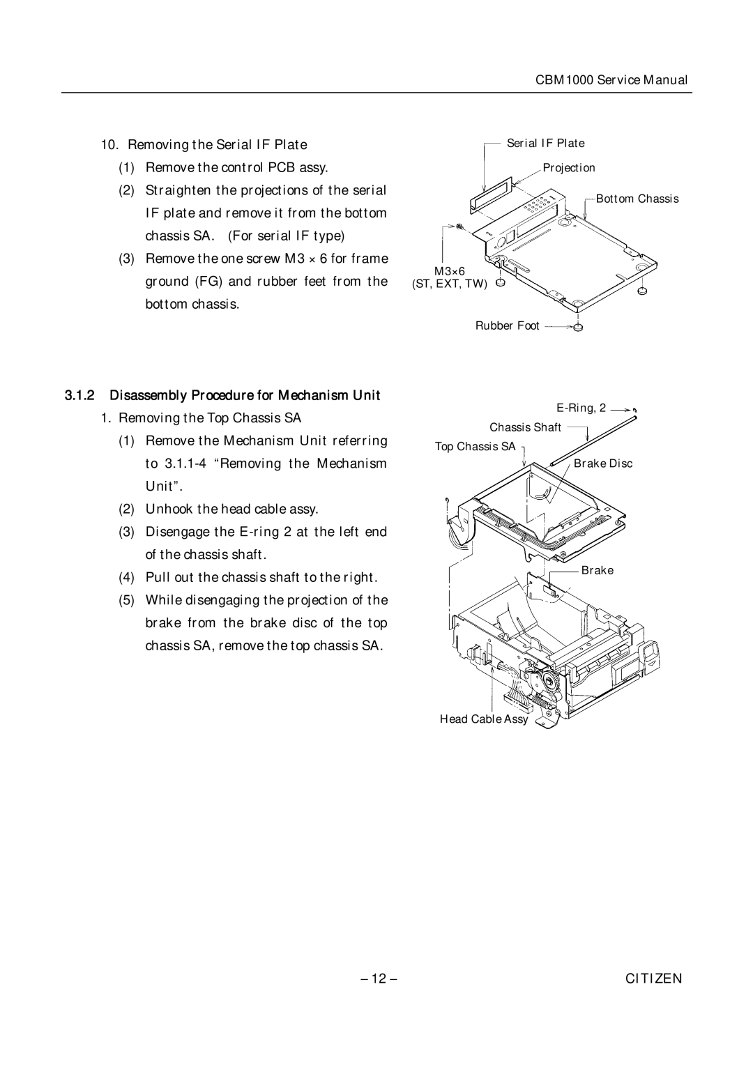
10.Removing the Serial IF Plate
(1)Remove the control PCB assy.
(2)Straighten the projections of the serial IF plate and remove it from the bottom chassis SA. (For serial IF type)
(3)Remove the one screw M3 × 6 for frame ground (FG) and rubber feet from the bottom chassis.
Serial IF Plate
Projection
Bottom Chassis
M3×6
(ST, EXT, TW)
Rubber Foot
3.1.2Disassembly Procedure for Mechanism Unit
1.Removing the Top Chassis SA
(1)Remove the Mechanism Unit referring to
(2)Unhook the head cable assy.
(3)Disengage the
(4)Pull out the chassis shaft to the right.
(5)While disengaging the projection of the brake from the brake disc of the top chassis SA, remove the top chassis SA.
Chassis Shaft
Top Chassis SA
Brake Disc
Brake
Head Cable Assy
– 12 – | CITIZEN |