CBM1000 Service Manual
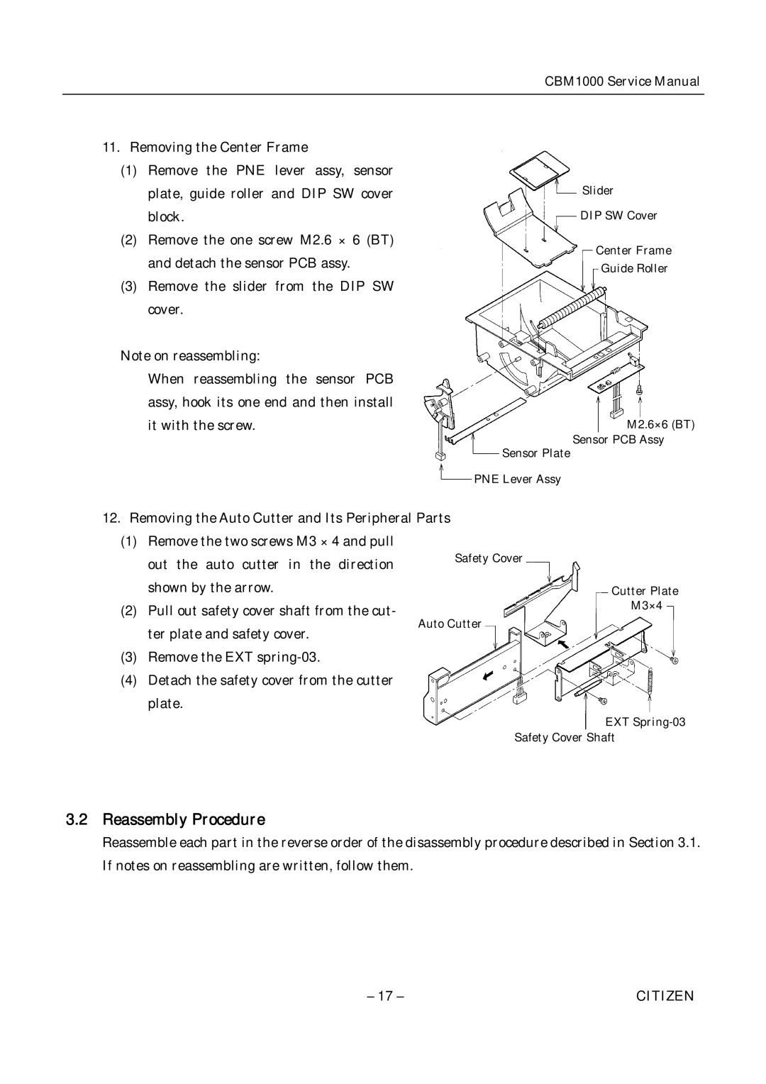
11.Removing the Center Frame
(1)Remove the PNE lever assy, sensor plate, guide roller and DIP SW cover block.
(2)Remove the one screw M2.6 × 6 (BT) and detach the sensor PCB assy.
(3)Remove the slider from the DIP SW cover.
Note on reassembling:
When reassembling the sensor PCB assy, hook its one end and then install it with the screw.
Slider
DIP SW Cover
Center Frame
Guide Roller
M2.6×6 (BT)
Sensor PCB Assy
Sensor Plate
PNE Lever Assy
12.Removing the Auto Cutter and Its Peripheral Parts
(1)Remove the two screws M3 × 4 and pull out the auto cutter in the direction shown by the arrow.
(2)Pull out safety cover shaft from the cut- ter plate and safety cover.
(3)Remove the EXT
(4)Detach the safety cover from the cutter plate.
Safety Cover
Cutter Plate
M3×4
EXT
Safety Cover Shaft
3.2 Reassembly Procedure
Reassemble each part in the reverse order of the disassembly procedure described in Section 3.1. If notes on reassembling are written, follow them.
– 17 – | CITIZEN |