5.3Description of Input/Output Signals
(1)Input signal
• DATA 1 to DATA 8 . . . 8 bit parallel signal (positive logic)
• STB . . . Strobe signal for reading out data (negative logic)
• RESET . . . Signal for resetting the entire unit (negative logic 4 ms or more)
(2)Output signal
• ACK . . . 8 bit data signal for requesting data. ACK is issued at the end of the BUSY signal (negative logic)
• BUSY . . . Signal indicating the printer is busy. Input new data when the signal is in “LOW” condition (positive logic)
• SELECT . . . Signal to indicate this equipment is in the SELECT (ready for communication) state (positive logic)
“LO”is output in the state deselected by the operation panel (SEL- SW), mechanical error, or memory error.
• P.N.E. . . . Signal to be output for
(3)Other
• GND . . . Ground commonly used in the circuit
• FRAME GND . . . Frame ground (case ground)
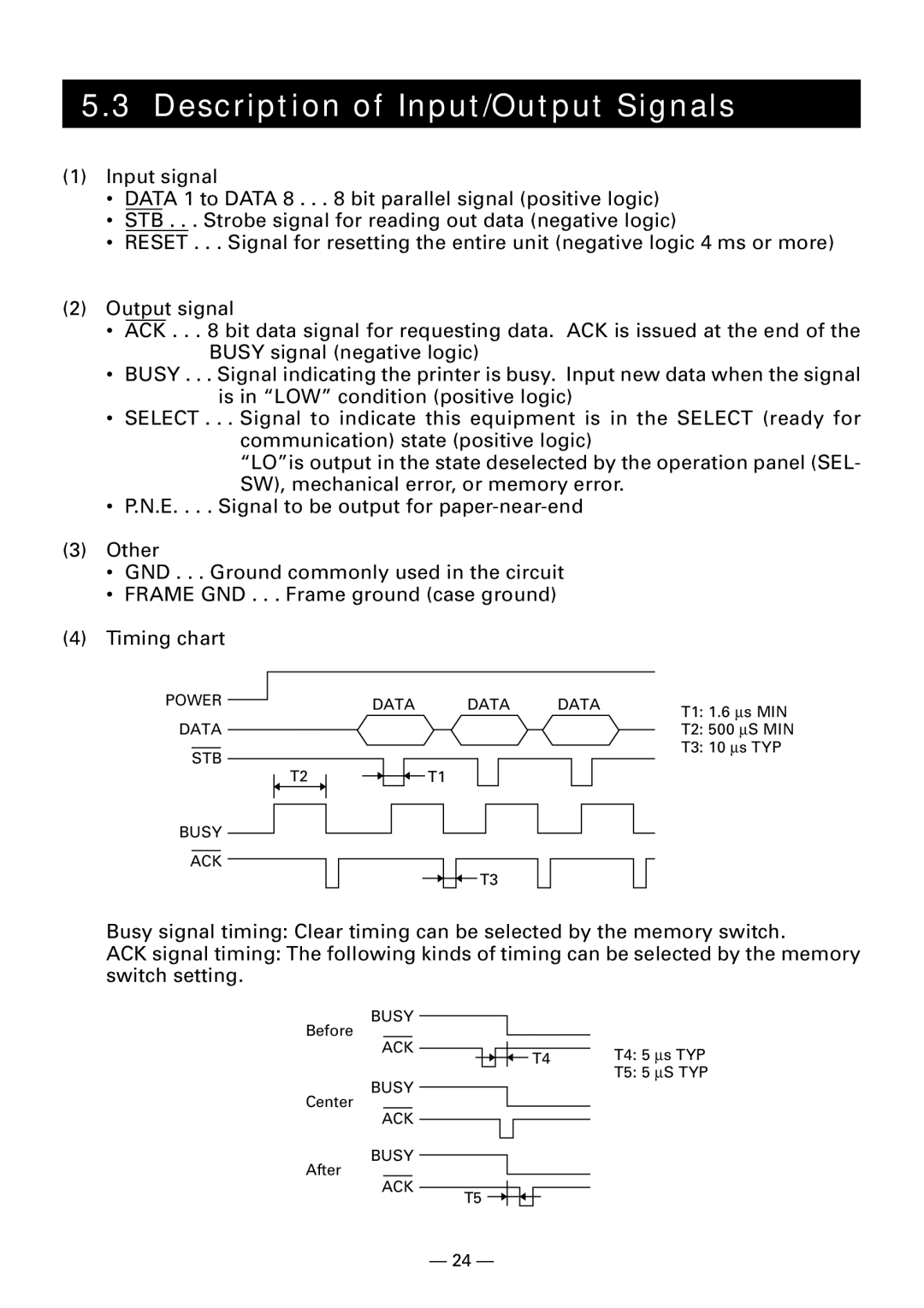
(4)Timing chart
POWER |
|
|
|
| DATA | DATA | DATA | T1: 1.6 ∝s MIN | ||||||||
|
|
|
| |||||||||||||
|
|
|
|
|
|
| ||||||||||
|
|
|
|
|
|
|
|
|
|
|
|
|
|
|
| |
DATA |
|
|
|
|
|
|
|
|
|
|
|
|
| T2: 500 ∝S MIN | ||
|
|
|
|
|
|
|
|
|
|
|
|
| ||||
|
|
|
|
|
|
|
|
|
|
|
|
|
|
|
| T3: 10 ∝s TYP |
| STB |
|
|
|
|
|
|
|
|
|
|
|
|
| ||
|
|
| T2 |
|
|
|
| T1 |
|
|
|
|
|
| ||
|
|
|
|
|
|
|
|
|
|
|
|
|
|
| ||
|
|
|
|
|
|
|
|
|
|
|
|
|
|
|
|
|
BUSY
ACK
T3
Busy signal timing: Clear timing can be selected by the memory switch.
ACK signal timing: The following kinds of timing can be selected by the memory switch setting.
BUSY
Before
ACK
BUSY
Center
ACK
BUSY
After
ACK
T5
T4 | T4: 5 | ∝s TYP |
| T5: 5 | ∝S TYP |
— 24 —