3.2 Connecting Interface Cables
Confirm that the power switch is OFF and connect the interface cable.
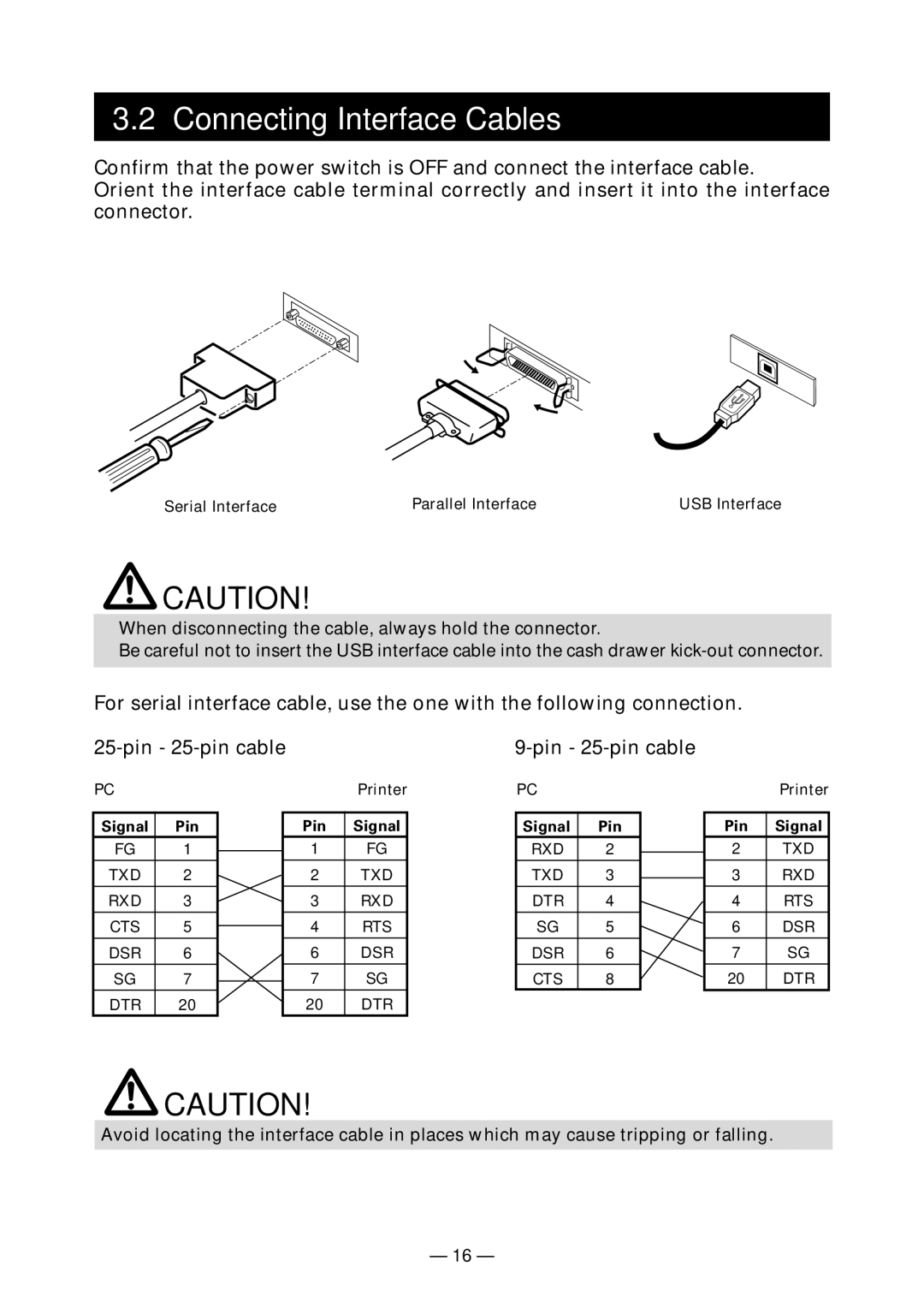
Orient the interface cable terminal correctly and insert it into the interface connector.
Serial Interface | Parallel Interface | USB Interface |
![]() CAUTION!
CAUTION!
■When disconnecting the cable, always hold the connector.
■Be careful not to insert the USB interface cable into the cash drawer
For serial interface cable, use the one with the following connection.
PC
Signal Pin
FG 1
TXD 2
RXD 3
CTS 5
DSR 6
SG 7
DTR 20
Printer
Pin | Signal |
1FG
2TXD
3RXD
4RTS
6DSR
7SG
20 DTR
PC
Signal | Pin |
RXD | 2 |
TXD | 3 |
DTR | 4 |
SG | 5 |
DSR | 6 |
CTS | 8 |
Printer
Pin Signal
2TXD
3RXD
4RTS
6DSR
7SG
20 DTR
![]() CAUTION!
CAUTION!
Avoid locating the interface cable in places which may cause tripping or falling.
— 16 —