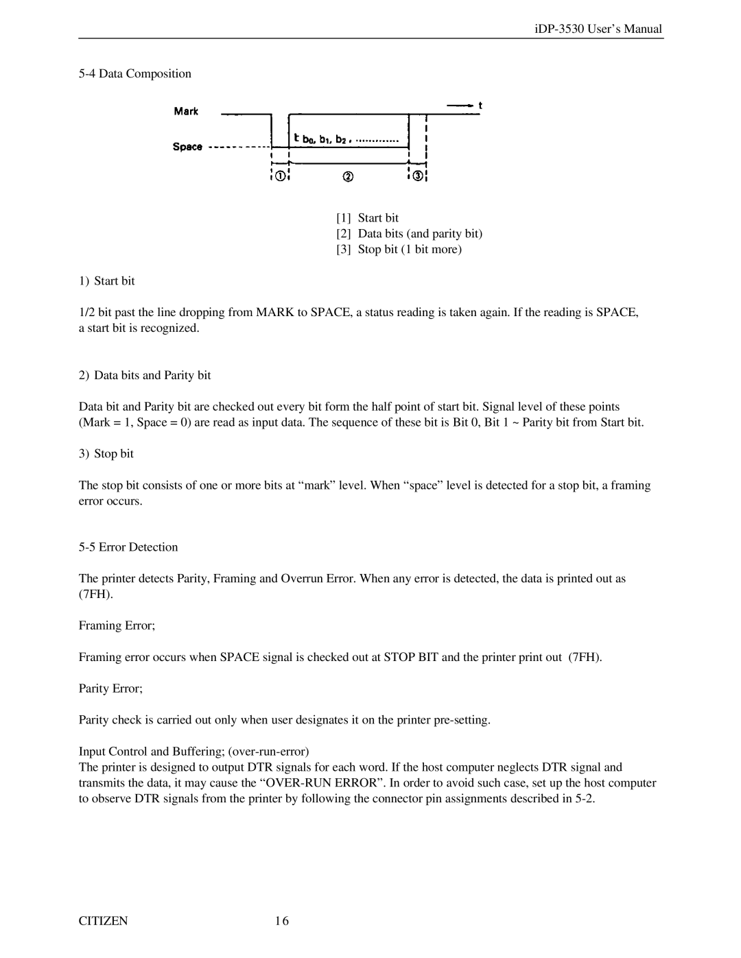
[1]Start bit
[2]Data bits (and parity bit)
[3]Stop bit (1 bit more)
1) Start bit
1/2 bit past the line dropping from MARK to SPACE, a status reading is taken again. If the reading is SPACE, a start bit is recognized.
2) Data bits and Parity bit
Data bit and Parity bit are checked out every bit form the half point of start bit. Signal level of these points (Mark = 1, Space = 0) are read as input data. The sequence of these bit is Bit 0, Bit 1 ~ Parity bit from Start bit.
3) Stop bit
The stop bit consists of one or more bits at “mark” level. When “space” level is detected for a stop bit, a framing error occurs.
The printer detects Parity, Framing and Overrun Error. When any error is detected, the data is printed out as (7FH).
Framing Error;
Framing error occurs when SPACE signal is checked out at STOP BIT and the printer print out (7FH).
Parity Error;
Parity check is carried out only when user designates it on the printer
Input Control and Buffering;
The printer is designed to output DTR signals for each word. If the host computer neglects DTR signal and transmits the data, it may cause the
CITIZEN | 16 |
