iDP3110 User's Manual
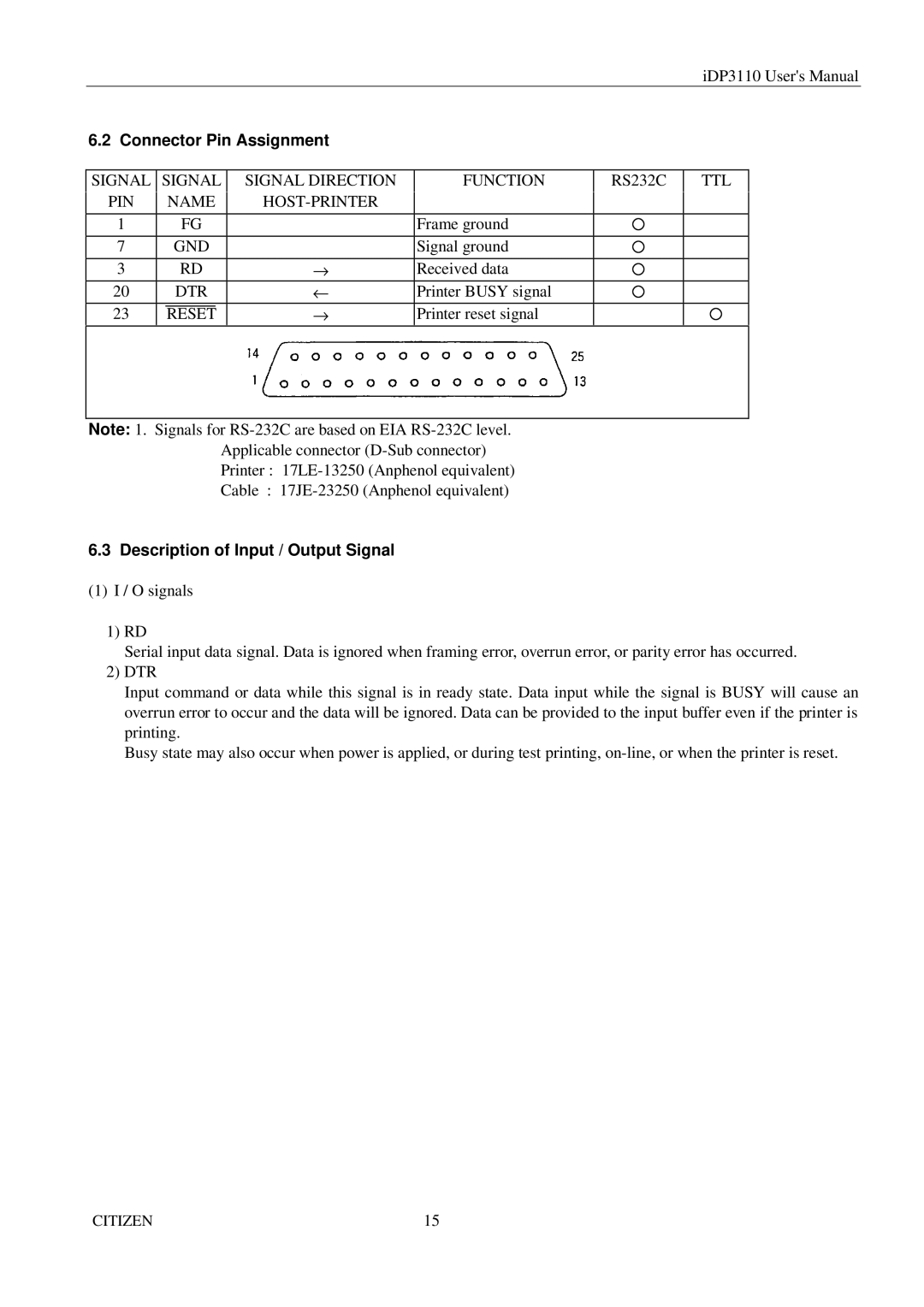
6.2 Connector Pin Assignment
SIGNAL | SIGNAL | SIGNAL DIRECTION | FUNCTION | RS232C | TTL | ||
PIN |
| NAME |
|
|
| ||
|
|
|
| ||||
|
|
|
|
|
|
|
|
1 |
| FG |
| Frame ground |
|
| |
|
|
|
|
|
|
|
|
7 |
| GND |
| Signal ground |
|
| |
|
|
|
|
|
|
|
|
3 |
| RD | → | Received data |
|
| |
|
|
|
|
|
|
|
|
20 |
| DTR | ← | Printer BUSY signal |
|
| |
|
|
|
|
|
|
|
|
23 |
|
|
| → | Printer reset signal |
|
|
| RESET |
|
| ||||
|
|
|
|
|
|
|
|
Note: 1. Signals for
Applicable connector
Printer :
Cable :
6.3 Description of Input / Output Signal
(1)I / O signals
1)RD
Serial input data signal. Data is ignored when framing error, overrun error, or parity error has occurred.
2)DTR
Input command or data while this signal is in ready state. Data input while the signal is BUSY will cause an overrun error to occur and the data will be ignored. Data can be provided to the input buffer even if the printer is printing.
Busy state may also occur when power is applied, or during test printing,
CITIZEN | 15 |