INSTALLATION
GENERAL
Installation of the unit must be accomplished by qualified electrical installation personnel working to all applicable local and national codes.
Improper installation of product could cause injury or damage.
This equipment is built to comply with applicable standards for manufacturers. Included among those approval agencies are: UL, NSF, ASME/Ntl. Bd., CSA, CGA, ETL, and others. Many local codes exist, and it is the responsibility of the owner/installer to comply with these codes.
Note: Maximum voltage for LVD (low volt direc- tive for Europe) to be 440 volts for CE marked appliances.
INSPECTION / UNPACKING
Note: The electrical rating label is located on the right console. Serial number, voltage, phase, amperage and wattage are stated on this label.
1.Before unpacking visually inspect the unit for evidence of damage during shipping.
2.If damage is noticed, do not unpack the unit, follow "SHIPPING DAMAGE INSTRUCTIONS" shown below.
3.Carefully remove unit from shipping carton. Remove any packing material from unit. After carefully unpacking check for "concealed" damage. If damage is noticed, follow "SHIPPING DAMAGE INSTRUCTIONS" shown below.
4.Check the electrical rating label to ensure that the unit is the correct voltage, phase, amper- age and wattage are stated on this label.
5.A protective material has been applied to the stainless steel panels. This material must be removed immediately after installation, as heat will melt the material and make it more difficult to remove.
SHIPPING DAMAGE
INSTRUCTIONS
If shipping damage to the unit is discovered or suspected, observe the following guidelines in preparing a shipping damage claim.
1.Write down a description of the damage or the reason for suspecting damage as soon as it is discovered. This will help in filling out the claim forms later.
2.As soon as damage is discovered or suspected, notify the carrier that delivered the shipment.
3.Arrange for the carrier's representative to examine the damage.
4.Fill out all carrier claims forms and have the examining carrier sign and date each form.
INSTALLATION
Note: For clearance requirements, suggested drain location and assembly details refer to "SPECIFICATION DRAWING" on page #3.
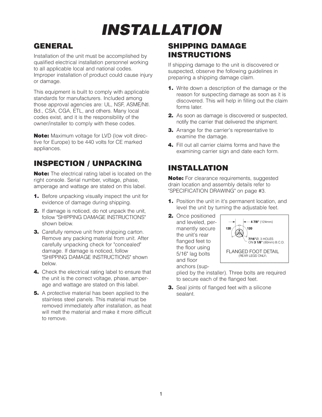
1.Position the unit in it's permanent location, and level the unit by turning the adjustable feet.
2.Once positioned
and leveled, per- |
|
|
|
|
|
| 4 7/8" (124mm) | |
|
|
| ||||||
manently secure | 120 |
|
| 120 | ||||
the unit's rear |
|
|
|
|
| 7/16"Ø, 3 HOLES | ||
flanged feet to |
|
|
|
|
| |||
|
|
|
|
| ON 3 1/8" (80mm) B.C.D. | |||
the floor using | FLANGED FOOT DETAIL | |||||||
5/16" lag bolts | ||||||||
|
|
| (REAR LEGS ONLY) | |||||
and floor |
|
|
|
|
|
|
| |
anchors (sup- |
|
|
|
|
|
|
| |
plied by the installer). Three bolts are required to secure each of the flanged feet.
3.Seal joints of flanged feet with a silicone sealant.
1