SROM Test Data Input Connector Pinouts
4.9 SROM Test Data Input Connector Pinouts
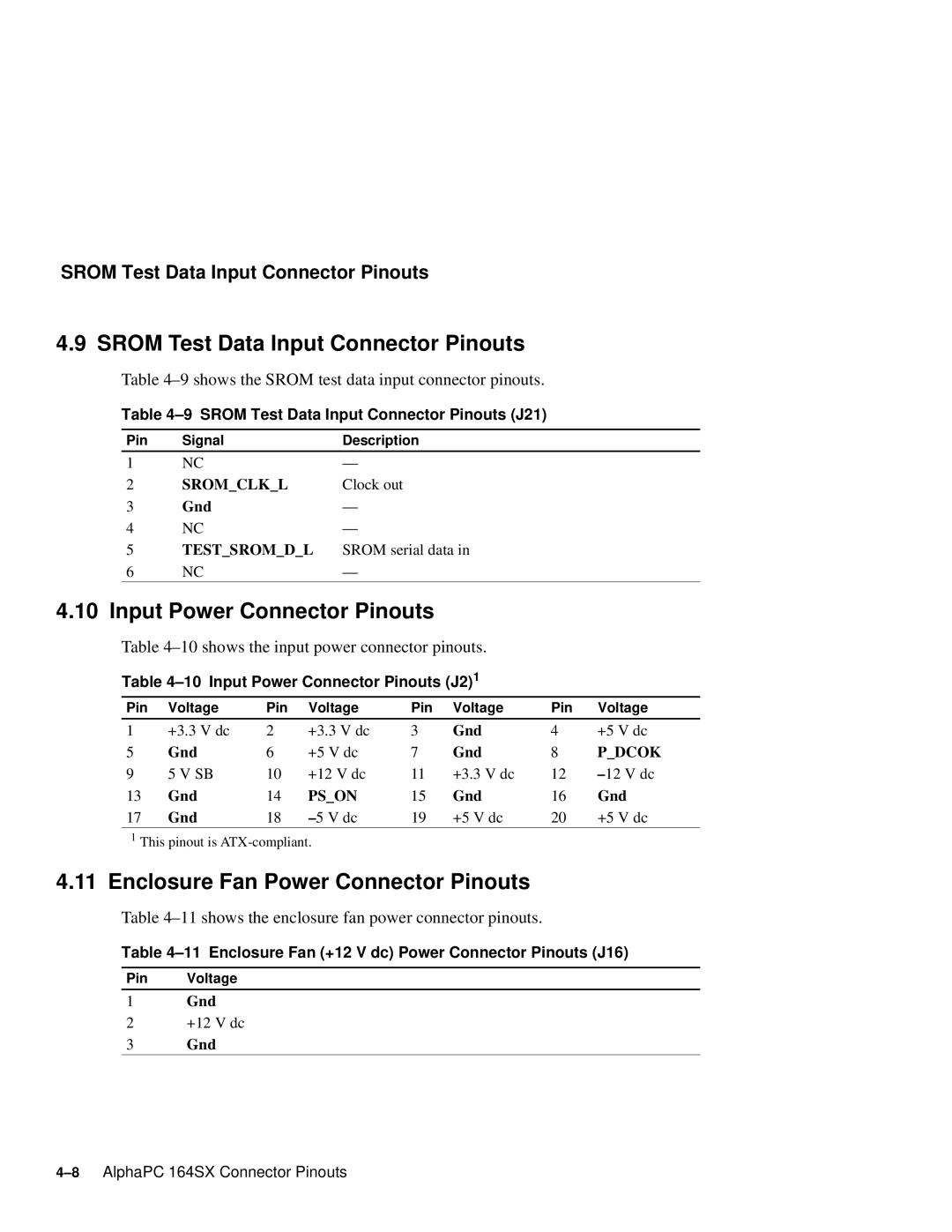
Table 4–9 shows the SROM test data input connector pinouts.
Table
Pin | Signal | Description |
1 | NC | — |
2 | SROM_CLK_L | Clock out |
3 | Gnd | — |
4 | NC | — |
5 | TEST_SROM_D_L | SROM serial data in |
6 | NC | — |
|
|
|
4.10 Input Power Connector Pinouts
Table 4–10 shows the input power connector pinouts.
Table 4–10 Input Power Connector Pinouts (J2) 1
Pin | Voltage | Pin | Voltage | Pin | Voltage | Pin | Voltage |
1 | +3.3 V dc | 2 | +3.3 V dc | 3 | Gnd | 4 | +5 V dc |
5 | Gnd | 6 | +5 V dc | 7 | Gnd | 8 | P_DCOK |
9 | 5 V SB | 10 | +12 V dc | 11 | +3.3 V dc | 12 | – 12 V dc |
13 | Gnd | 14 | PS_ON | 15 | Gnd | 16 | Gnd |
17 | Gnd | 18 | – 5 V dc | 19 | +5 V dc | 20 | +5 V dc |
1This pinout is
4.11Enclosure Fan Power Connector Pinouts
Table 4–11 shows the enclosure fan power connector pinouts.
Table
Pin Voltage
1Gnd
2+12 V dc
3Gnd