KVM Switch 
The connectors (keyboard, mouse and monitor) at the Local port on the rear of the KVM module are not applicable when the module is connected to the drawer by the
Initial Power-Up
Make sure all computers and the StreamLine KVM switches are powered down during installation. You must power up the Master StreamLine before turning on any other devices.
nFor single StreamLine KVM switch:
1)Apply a power adapter to the Master.
2)Turn on computers.
nFor cascaded StreamLine KVM switches:
1)Apply a power adapter to the Master.
2)Apply power adapters to all Slaves.
3)Turn on computers.
Note: You may hot plug additional
------------------------ Operation
Front Panel Push Buttons
A computer may be selected by pressing the front panel push button directly, by issuing
nK/M RESET
K/M RESET solves most problems developed by keyboard, mouse, device replacement or change of configuration. Press down both the
7
KVM Switch 
computer off.
nAUTO SCAN
StreamLine KVM switches provide an easy to use feature to start Auto Scanning. You can press down both the
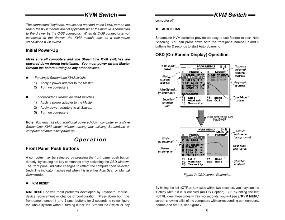
OSD (On-Screen-Display) Operation
Figure 7: OSD screen illustration
By hitting the left <CTRL> key twice within two seconds, you may see the 'Hotkey Menu' if it is enabled (an OSD option). Or, by hitting the left <CTRL> key three times within two seconds, you will see a 'KVM MENU' screen showing a list of the computers with corresponding port numbers, names and status, see figure 7.
8
