139.53626SR - I/2HP, 139.53515SR - I/2HP specifications
The Craftsman 139.53626SR and 139.53515SR are two remarkable garage door openers that deliver reliable performance and advanced features ideal for both residential and commercial applications. Both models are powered by a robust ½ horsepower motor, providing a strong lift capability that can handle various types of garage doors.One of the main features of the Craftsman 139.53626SR is its quiet operation. Designed with a belt drive system, it minimizes noise while delivering consistent performance. This makes it an excellent choice for homes where the garage is attached to the living space. The unit is also equipped with a soft-start and soft-stop feature, which ensures gentle movement of the door, further reducing noise and extending the lifespan of the garage door system.
The Craftsman 139.53515SR, on the other hand, incorporates a chain drive mechanism which is known for its durability and strength. This model is perfect for heavier doors or commercial applications where durability is crucial. It is built to withstand the rigors of frequent use and features a robust frame designed for long-lasting performance.
Both models include advanced safety features such as the infrared safety sensors that prevent the door from closing if something is detected in its path, thereby reducing the risk of accidents. They also come with a multi-function wall console, allowing for easy operation and access to settings like the vacation lock and door light control.
In terms of technology, the Craftsman openers are equipped with a security code system that changes the access code each time the remote is used. This feature enhances security by minimizing the risk of unauthorized access. Furthermore, both models are compatible with smartphone control options when paired with additional Craftsman connectivity accessories, providing users with the convenience of operating their garage doors remotely.
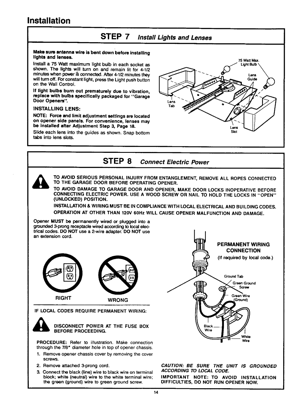
Setting up the Craftsman 139.53626SR and 139.53515SR is straightforward, thanks to the included installation manuals and clear instructions. Both models are designed for easy installation, making them ideal for DIY enthusiasts.
Overall, whether you choose the 139.53626SR for its quiet performance or the rugged 139.53515SR for its strength, both Craftsman garage door openers deliver reliability, advanced features, and safety, making them excellent additions to any home or business.

