Abridor DE Puerta DE Cochera DE 315MN=
Contents
Introduction
Tools needed
Preparing your garage door
Sectional Door Installation
Sectional Door Installations
Planning
Finished Ceiling
ONE-PIECE Door Installations
ONE-PIECE Door Without Track
ONE-PIECE Door with Track
Finished Ceung
Carton Inventory
SECURITY+
Hardware Inventory
Assembly Hardware
Installation Hardware
Assembly Step
Assemble the Rail
Hardware Shown Actual Size
Fasten the Rail to the Motor Unit Install the Trolley
Attach the Rail Brackets
Installation
Readand Followall Installationwarningsand Instructions
Installation Step
Determine the Header Bracket Location
Ceiling Header Bracket Installation
Install the Header Bracket
Wall Header Bracket Installation
Attach the Rail to the Header Bracket
Install The Protector System
Important Information about Safety Reversing Sensor
Installing the Brackets
Garage door track installation preferred
Wall installation
Floor installation Figure
Mounting and Wiring the Safety Sensors
Recommended Wire Routing
Engaged Released
Position the Opener
Sectional Door or ONE-PIECE Door with Track
Hang the Opener
Fenshed Ceung Hardware Shown Actual Size
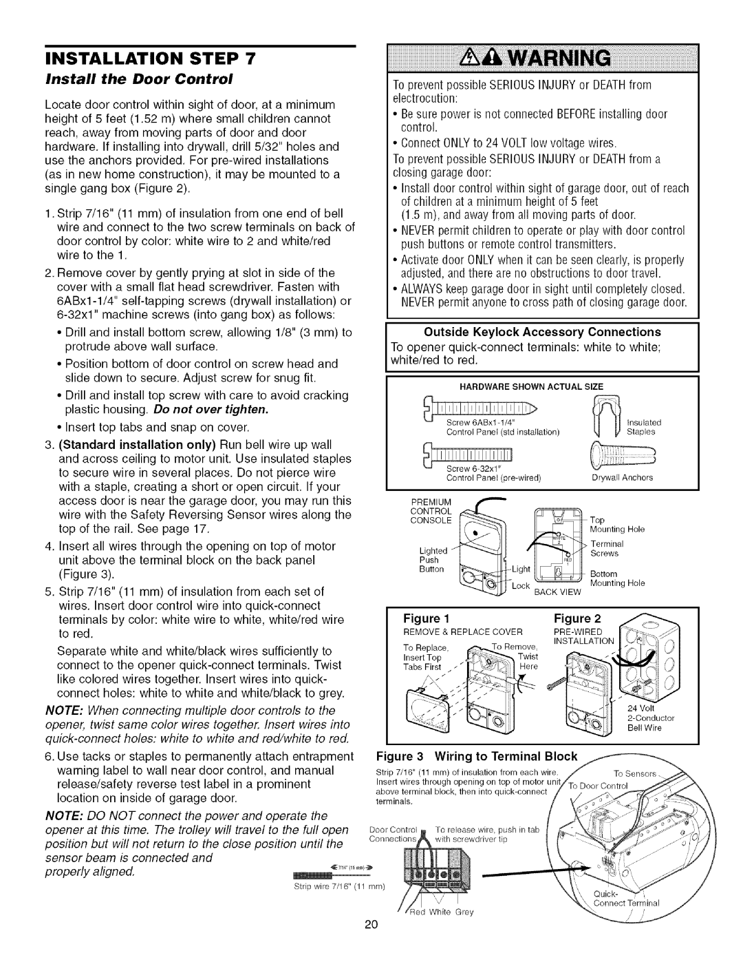
Install Door Control
Complete the Safety Reversing Sensor Installation
Aligning the Safety Reversing Sensors
Troubleshooting the Safety Reversing Sensors
Permanent Wiring Connection
Install the Lights
Attach the Emergency Release Rope and Handle
Fasten the Door Bracket
Sectional Doors
ONE-PIECEDOORS
Connect Door Arm to Trolley
Sectional Doors only
Adjustment procedures, Figure
ALL ONE-PIECE Doors
Assemble the door arm, Figure
Connect the door arm to the trolley
Adjustment Step
Adjust the Travel Limits
HOW and When to Adjust the Limits
If door does not open at least 5 feet 1.5 m
Adjust the Force
HOW and When to Adjust the Forces
Test the Down close force
Test the UP open force
Test the Safety Reversal System
Adjust
Important Safety Check
Test The Protector System
Readand Followall Warningsand Instructions
Using Your Garage Door Opener
Operation
To Open the Door Manually
Using the Wall.Mounted Door Control
Light feature
Remote Control Battery
Care of Your Opener
Once a Month
Once a Year
Having a PROBLEM?
Refer to Adjustment , Adjust the Force
Symptom LED is not lit on door control
Symptom Motor unit doesnt operate
To Add or Reprogram a Hand-held Remote Control
Using the Learn Button Using the Premium Control Console
Programming
To Erase All Codes From Motor Unit Memory
To Add Reprogram Change Keyless Entry PIN
Must be programmed To operate Your Garage door Opener
Entry is already mounted outside the garage
To change an existing, known PIN
Repair Parts
Rail Assembly Parts Installation Parts
KEY Part NO. NO. Description
Not Shown
KEY Part NO. NO.DESCRIPTION
Motor Unit Assembly Parts
KEY Part
Accessories
Warranty
Service
For Sectional Doors Only
Contenido
Introduccion
Preparaci6n de la puerta de su cochera
Herramientas necesarias
Planificaci6n
Instalacicn CON UNA Puerta Seccional
Instalacion EN UNA Puerta Seccional
Techo TERMI/ADO
Planificaci6n continba
Instalacion CON Puertas DE UNA Sola Pieza
Puerta DE UNA Sola Pieza SIN Carril
Puerta DE UNA Pieza CON Carril
Inventario de las caja de cart6n
Inventario de Piezas
Tornillera Y Piezas Para EL Montaje
Montaje Paso
Monte el riel
Montaje el riel continba
Estas Piezas SE Muestran EN SU Tamano Real
Fije el riel a la unidad del motor e instale el trole
Estas Piezas SE Muestran EN SU Tamaiio Real
LA Muerte
Fijacibn de las mnsulas del riel
Instalacion Paso
Determine dbnde va a instalar la Mnsula del Cabezal
Cabezal
Eltecho
Instale la mnsula del cabezal
Instalacion DE LA Mensula DEL Cabezal EN EL
Colocacibn del riel en la mnsula del cabezal
Estas Piezas SE Muestran EN SU Tamaiio Real
Instale la Sistema de Protecci6n
Enfrentando la puerta desde el lado interno del garaje
Instalacion DE LAS Mcnsulas
Instalaci6n en la pared Figura 2 y
Instalaci6n en el piso Figura
Montajeparedlado Derecho
Ruta recomendada para el cableado
Enganchado Desenganchado
Coloque el Abridor en Posici6n
Puerta DE UNA Sola Pieza SIN Riel
INSTALACION, Paso
Cuelgue el Abridor
Quitar Y Volvera Ponerlatapa
Instale la unidad de control de la puerta
Estas Piezas SE Muestran EN SU Tamaio Real
Requisitos para la instalaci6n el6ctrica
COMe Alinear LOS Sensores DE Seguridad
Instale las Luces
Coloque la Cuerda y la Manija De Emergencia
Fije la mnsula de la puerta
Puertas Seccionales
Puertas DE UNA Sola Pieza
Conecte el brazo de la puerta al trole
SLO Para Puertas Seccionales
Todas LAS Puertas DE UNA Sola Pieza
Arme el brazo de la puerta, Figura
Calcomanade Ajustes
Ajustes Paso
Ajuste el limite del recorrido Hacia Arriba y Hacia Abajo
Ajuste de la fuerza
Etiouetade Ajustede Fuerza
Pruebe la Sistema de Protecci6n
Pruebe el Sistema de Retroceso de Seguridad
Prueba
Ajuste
Conserveestasinstrucciones
Operacion
C6mo Usar su Abridor de Puerta de Cochera
Active su abridor de alguna de las siguientes maneras
C6mo usar la unidad de control de pared
C6mo abrir la puerta manualmente
Como Desconectar EL Trole
CMO Reconectar EL Trole
Mantenimiento DE SU Abridor DE Puerta DE Cochera
Ajustes DE Lmite Y Fuerza
SI Tiene Algon Problema
El control remoto no activa la puerta
Tabla de Diag
El motor
Controles Remotos de 3 Funciones
Como Programar EL Abridor
C6mo Agregar o Reprogramar un Control Remoto Manual
Para cambiar un PIN existente
Accesorios
Riel de 2.4 m 8 pies
No.,a,,erw.orna1,,noe.,a,,erw.so,1