MOTOR AND BLOWER
TO BASE ASSEMBLY
MAKE CERTAIN THE DUST COLLECTOR IS DISCONNECTED FROM THE POWER SOURCE.
1, Place motor and blower assembly and base on their side with intake port pointing towards base,
5, Figure 9 shows the motor and blower assembly attached to the side supports,
SUPPORT ASSEMBLY
MAKE CERTAIN THE DUST COLLECTOR IS DISCONNECTED FROM THE POWER SOURCE.
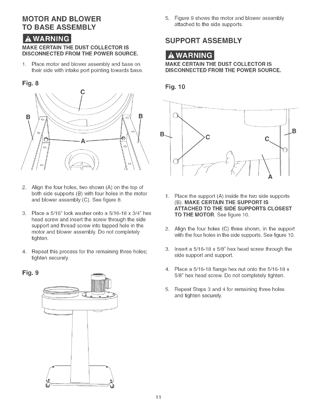
Fig. 8
Fig. 10
C
BB
_B
B_
A
c
A
2, Align the four hobs, two shown (A) on the top of both side supports (B) with four holes in the motor
1,
and blower assembly (C), See figure 8,
8, Place a 5/16" lock washer onto a
head screw and insert the screw through the side support and thread screw into tapped hob in the
2,
motor and blower assembly, Do not completely tighten,
8,
4, Repeat this process for the remaining three hobs; tighten securely,
4,
Fig. 9
5,
Place the support (A) inside the two side supports
(B), MAKE CERTAIN THE SUPPORT IS ATTACHED TO THE SIDE SUPPORTS CLOSEST TO THE MOTOR, See figure 10,
Align the four hobs (C) three shown, in the support with the four hobs in the side supports, See figure 10,
insert a
Place a 5/16=18 flange hex nut onto the 5/16=18 x 5/8" hex head screw, Do not completely tighten,
Repeat Steps 3 and 4 for remaining three hobs and tighten securely,
11