•Level the frame assembly and tip the auger housing forward to align studs with the corresponding holes on both sides of the frame assembly. See Figure 27. Push the frame assembly fully on to the studs.
NOTE: Use care to avoid pinching the control cable.
•From the frame assembly side, insert six lock washers and hex nuts on to the studs. These pieces of hardware were removed earlier. See Figure 27. Tighten the nuts securely.
•Reinstall the belt cover on front of the engine with the two
•Reattach the chute crank to the chute assembly with the hairpin clip and flat washer.
NOTE: Make sure that the auger cable is routed in front of the belt.
Drive Belt
•Check drive belt every 50 hours of operation for wear and tear.
•Drain the gasoline from the snow thrower, or place a piece of plastic under the gas cap.
•Remove the plastic belt cover on the front of the engine by removing the two
•Tip the snow thrower up and forward, so that it rests on the housing.
•Remove six
•Pull the idler pulley away from the drive belt and remove the belt from the engine pulley. You will find the idler pulley in front of the engine and under the belt cover that you removed earlier.
•Working from the underside of the frame, slip belt between the friction wheel and the friction wheel disc. See Figure 31. You may have to twist the belt flat in order to slide it through the clearance between the friction wheel and the friction wheel disc. Remove the belt.
•Install new belt. Reassemble following the instructions in reverse order.
Friction
Wheel
Idler
Pulley
Location
Friction | Drive Belt |
Wheel | Location |
Disc |
|
Figure 31
Changing Friction Wheel Rubber
•Check the rubber on the friction wheel after 25 hours of operation, and periodically thereafter. Replace the rubber if any signs of wear or cracking are found.
•Drain the gasoline from the snow thrower, or place a piece of plastic under the gas cap.
•Tip the snow thrower up and forward, so that it rests on the housing.
•Remove six screws from the frame cover underneath the snow thrower.
•Remove klick pin securing the left wheel, and remove the wheel from the axle.
•Remove the four screws securing the left drive cover to the frame. The drive cover is located behind the wheel chain case. Remove the drive cover from the side of the frame. See Figure 32.
Drive
Cover
Figure 32
•Holding the friction wheel assembly, slide the hex shaft out of the left side of the unit. The spacer on the right side of the hex shaft will fall and the sprocket should remain hanging lose in the chain.
•Lift the friction wheel assembly out between the axle shaft and the drive shaft assemblies.
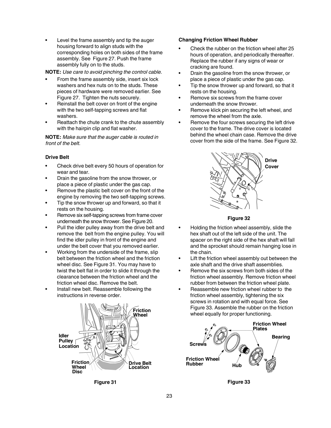
•Remove the six screws from both sides of the friction wheel assembly. Remove friction wheel rubber from between the friction wheel plate.
•Reassemble new friction wheel rubber to the friction wheel assembly, tightening the six screws in rotation and with equal force. See Figure 33. Assemble the rubber on the friction wheel equally for proper functioning.
Friction Wheel
Plates
Bearing
Screws
Friction Wheel
RubberHub
Figure 33
23