•Secure the ferrule to the shift lever with another 5/16 flat washer and hairpin clip from group D of the hardware pack. See Figure 11.
•Make certain to check for correct adjustment of the shift rod as instructed in the Adjustment section before operating the snow thrower.
Attaching Turn Triggers
•Check and make sure that the right hand trigger cable is routed in front of the traction drive cable.
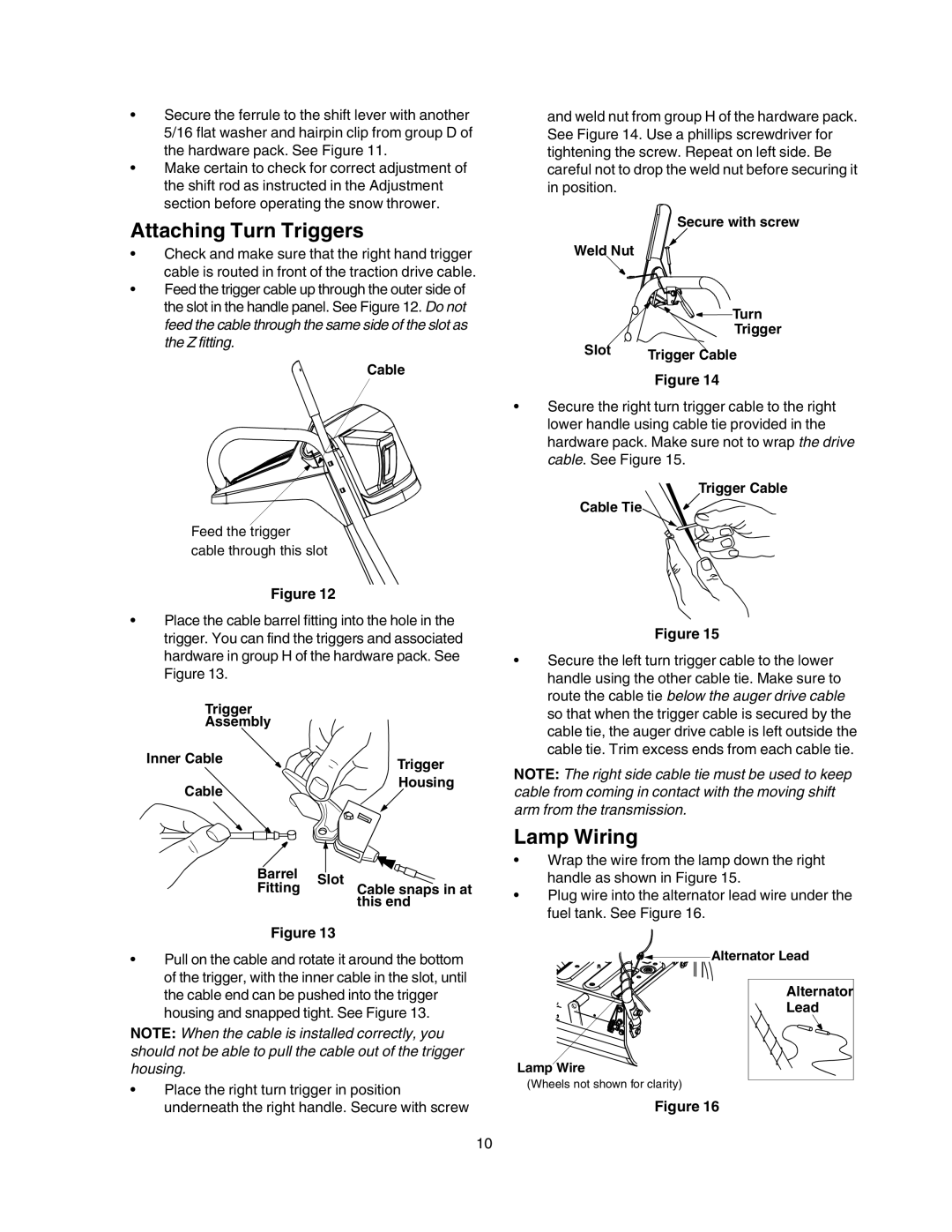
•Feed the trigger cable up through the outer side of the slot in the handle panel. See Figure 12. Do not feed the cable through the same side of the slot as the Z fitting.
Cable
Feed the trigger cable through this slot
Figure 12
•Place the cable barrel fitting into the hole in the trigger. You can find the triggers and associated hardware in group H of the hardware pack. See Figure 13.
Trigger
Assembly
Inner Cable | Trigger |
| |
Cable | Housing |
|
Barrel |
|
| |
Slot | |||
Fitting | |||
| Cable snaps in at | ||
|
| this end | |
Figure 13
• | Pull on the cable and rotate it around the bottom |
| of the trigger, with the inner cable in the slot, until |
and weld nut from group H of the hardware pack. See Figure 14. Use a phillips screwdriver for tightening the screw. Repeat on left side. Be careful not to drop the weld nut before securing it in position.
Secure with screw
Weld Nut
![]()
![]()
![]()
![]() Turn
Turn
Trigger
Slot | Trigger Cable |
|
Figure 14
•Secure the right turn trigger cable to the right lower handle using cable tie provided in the hardware pack. Make sure not to wrap the drive cable. See Figure 15.
Trigger Cable
Cable Tie
Figure 15
•Secure the left turn trigger cable to the lower handle using the other cable tie. Make sure to route the cable tie below the auger drive cable so that when the trigger cable is secured by the cable tie, the auger drive cable is left outside the cable tie. Trim excess ends from each cable tie.
NOTE: The right side cable tie must be used to keep cable from coming in contact with the moving shift arm from the transmission.
Lamp Wiring
•Wrap the wire from the lamp down the right handle as shown in Figure 15.
•Plug wire into the alternator lead wire under the fuel tank. See Figure 16.
![]()
![]()
![]()
![]() Alternator Lead
Alternator Lead
the cable end can be pushed into the trigger |
housing and snapped tight. See Figure 13. |
NOTE: When the cable is installed correctly, you should not be able to pull the cable out of the trigger housing.
•Place the right turn trigger in position underneath the right handle. Secure with screw
Lamp Wire
(Wheels not shown for clarity)
Figure 16
Alternator |
Lead |
10