Assemblyisbestdonein theareawherethesawwill beused.Whenyouremovethesawandhardware fromthepackingmaterials,carefullychecktheitems withtheLoosePartslist.Ifyouareunsureaboutthe descriptionof anypart,refertotheirillustrationsFor. yourconvenience,allfastenershavebeendrawn actualsize.Ifanypartsaremissing,delayassembling untilyouhaveobtainedthemissingpart(s).
Yourradialarmsawiscapableofawidevarietyof operations,andthusrequiresanumberof initialsetup adjustmentsHowever,oncethesawissetup,you. cancheckyoursawinabouttenminutesandcorrect anymisalignmentwiththeproceduresin theAdjust-
ment section.
_ CAUTION: Perform all the procedures in both the Assembly and Adjustments sections before
using the saw. Run a check on your saw frequently, referring to the Adjustments section. Failure to perform the adjustments in the initial set up or on a frequent basis can result in poor performance or machine damage.
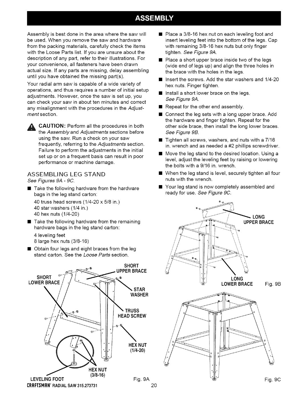
ASSEMBLING LEG STAND
See Figures 9A - 9C.
•Take the following hardware from the hardware bags in the leg stand carton:
40 truss head screws
40 star washers (1/4 in.)
40 hex nuts
•Take the following hardware from the remaining hardware bags in the leg stand carton:
4 leveling feet
8 large hex nuts
•Obtain four legs and eight braces from the leg stand carton. See the Loose Parts section.
SHORT
IPPERBRACE
SHORT
LOWERBRACE
WASHERSTAR
TRUSS
HEABSCREW
| HEXNUT |
| |
HEXNUT |
|
Fig. 9A | |
LEVELINGFOOT | |
CR_F;T=_MRN°RADIALSAW315.273731 | 20 |
•Place a
•Place a short upper brace inside two of the legs (wide end of legs up) and align the three holes in the brace with the holes in the legs.
•Insert the screws. Add the star washers and
•Install a short lower brace on the legs. See Figure 9A.
•Repeat for the other end assembly.
•Connect the leg sets with a long upper brace. Add the hardware and finger tighten. Repeat for the other side brace, then install the long lower braces. See Figure 9B.
•Tighten all screws, washers, and nuts with a 7/16 in. wrench and as needed a #2 phillips screwdriver.
•Move the leg stand to the desired location. Using a level, adjust the leveling feet by raising or lowering the bolts with a 9/16 in. wrench.
•When the leg stand is level, securely tighten all four nuts with the wrench.
•Your leg stand is now completely assembled and ready for use. See Figure 9C.
LONG
UPPERBRACE
LONG
LOWERBRACE Fig. 9B
Fig. 9C