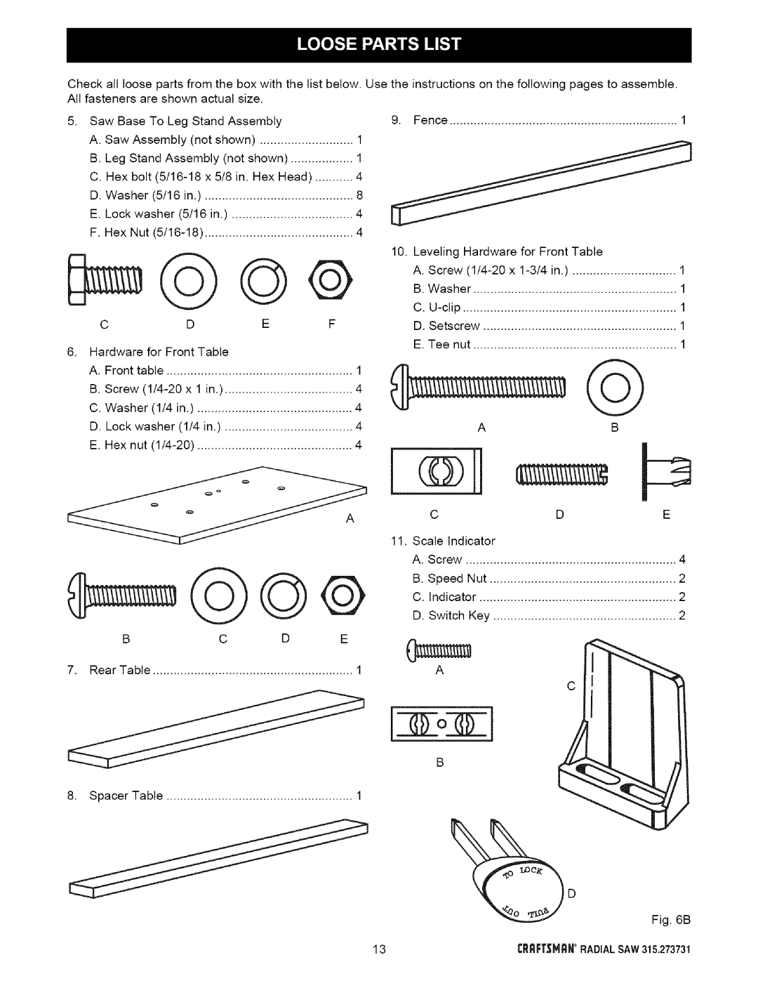
Check all loose parts from the box with the list below. All fasteners are shown actual size.
5.Saw Base To Leg Stand Assembly
A. Saw Assembly (not shown) | 1 | |
B. Leg Stand Assembly (not shown) | 1 | |
C. Hex bolt | x 5/8 in. Hex Head) | 4 |
D. Washer (5/16 in.) | ........................................... | 8 |
E. Lock washer (5/16 | in.) | 4 |
F. Hex Nut | ........................................... | 4 |
Use the instructions on the following pages to assemble.
9. Fence | 1 |
C | D | E | F |
. Hardware for Front Table |
|
| |
A. Front table |
| 1 | |
B. Screw | x 1 in.) | ..................................... | 4 |
C. Washer (1/4 in.) | 4 | ||
D. Lock washer | (1/4 in.) | ..................................... | 4 |
E. Hex nut | 4 | ||
B | C | D | E |
7. Rear Table | .......................................................... | 1 | |
10. Leveling Hardware for Front Table |
|
A. Screw | 1 |
B. Washer | 1 |
C. | 1 |
D. Setscrew | 1 |
E. Tee nut | 1 |
@
| A |
| B |
®H |
|
| |
C |
| D | E |
11. Scale Indicator |
|
| |
A. Screw | ............................................................. | 4 | |
B. Speed | Nut | 2 | |
C. Indicator | 2 | ||
D. Switch | Key | 2 | |
A |
|
|
|
|
|
| C |
o J
8. Spacer Table | 1 |
Fig. 6B
13rRRFTSMRNRADIALSAW315.273731