ALIGNING THE ARM FOR CROSS CUTS
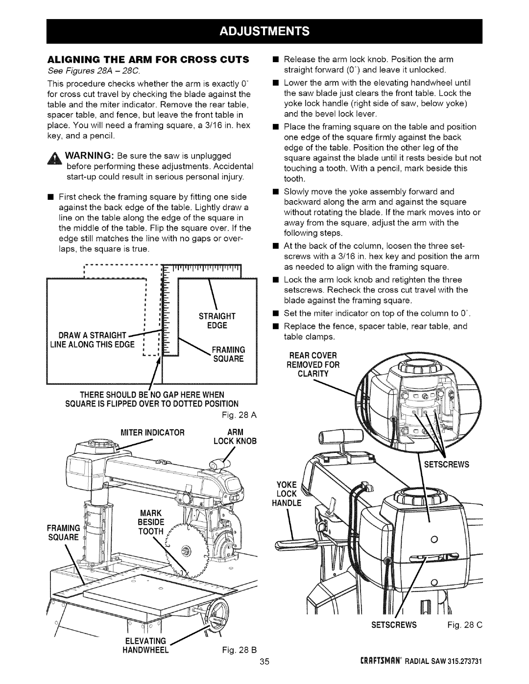
See Figures 28A - 28C.
This procedure checks whether the arm is exactly 0° for cross cut travel by checking the blade against the table and the miter indicator. Remove the rear table, spacer table, and fence, but leave the front table in place. You will need a framing square, a 3/16 in. hex key, and a pencil.
,_ WARNING: Be sure the saw is unplugged before performing these adjustments. Accidental
•First check the framing square by fitting one side against the back edge of the table. Lightly draw a line on the table along the edge of the square in the middle of the table. Flip the square over. If the edge still matches the line with no gaps or over- laps, the square is true.
•Release the arm lock knob. Position the arm straight forward (0°) and leave it unlocked.
•Lower the arm with the elevating handwheel until the saw blade just clears the front table. Lock the yoke lock handle (right side of saw, below yoke) and the bevel lock lever.
•Place the framing square on the table and position one edge of the square firmly against the back edge of the table. Position the other leg of the square against the blade until it rests beside but not touching a tooth. With a pencil, mark beside this tooth.
•Slowly move the yoke assembly forward and backward along the arm and against the square without rotating the blade. If the mark moves into or away from the square, adjust the arm with the following steps.
•At the back of the column, loosen the three set- screws with a 3/16 in. hex key and position the arm as needed to align with the framing square.
•Lock the arm lock knob and retighten the three setscrews. Recheck the cross cut travel with the blade against the framing square.
STRAIGHT
EDGE
DRAWA STRAIGHT
LINEALONGTHIS EDGE ,
mFRAMING
SQUARE
THERESHOULDBE NOGAP HEREWHEN SQUAREIS FLIPPEDOVERTO DOTTEDPOSITION
Fig. 28 A
MITERINDICATORARM
LOCKKNOB
/
•Set the miter indicator on top of the column to 0°.
•Replace the fence, spacer table, rear table, and table clamps.
REARCOVER
REMOVEDFOR
CLARITY
SETSCREWS
) YOKE
LOCK
HANDLE
FRAMING
SQUARE
SETSCREWS Fig. 28 C
ELEVATING |
|
HANDWHEEL | Fig. 28 B |
35 | CRRFT=_MRN° RADIAL SAW315.273731 |