Craftsman 315.273731 Aligning the RIP Scale Indicators, See Figures 32A 32B, Yokepivot Latch

Models: 315.273731

1 80
Download 80 pages 61.15 Kb
Page 39
Image 39

ALIGNING THE RIP SCALE INDICATORS

See Figures 32A - 32B.

The rip scale indicators on the arm show the distance between the blade and the rip fence. The upper scale

is used when the fence is positioned directly behind the front table. The lower scale is used when the

fence is at the extreme rear, directly in front of the column.

The in-rip indicator and scale are on the right side of

the arm. The out-rip indicator and scale are on the left side.

This procedure checks the indicators with the fence at the back of the tables directly in front of the column. The blade should be turned to the in-rip position to set the rip scale indicator on the right side of the arm. Then, the blade should be turned to the out-rip position to set the rip scale indicator on the left side of the arm. You will need a framing square.

If the fence is not at the rear of the tables, place it there.

Turn the blade to the in-rip position by loosening the yoke lock handle, below the arm on the right. Then pull the yoke pivot latch forward and rotate the yoke to the in-rip position. This indexes the yoke 90 ° so the blade is between the motor and the column. Lock the yoke lock handle.

With the elevating handwheel, lower the arm until the blade just clears the table.

Loosen the carriage lock knob and guide the blade back to just touch the fence. Tighten the carriage lock knob.

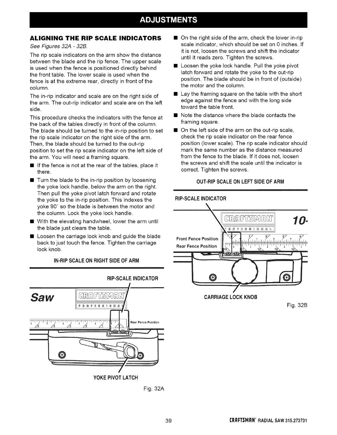
IN-RIPSCALEON RIGHTSIDEOF ARM

RIP-SCALEINDICATOR

On the right side of the arm, check the lower in-rip scale indicator, which should be set on 0 inches. If it is not, loosen the screws and shift the indicator until it reads zero. Tighten the screws.

Loosen the yoke lock handle. Pull the yoke pivot latch forward and rotate the yoke to the out-rip position. The blade should be in front of (outside) the motor and the column.

Lay the framing square on the table with the short edge against the fence and with the long side toward the table front.

Note the distance where the blade contacts the framing square.

On the left side of the arm on the out-rip scale, check the rip scale indicator on the rear fence position (lower scale). The rip scale indicator should mark the same number as the distance measured from the fence to the blade. If it does not, loosen the screws and shift the scale until the indicator is correct. Tighten the screws.

OUT-RIPSCALEON LEFTSIDEOF ARM

RIP-SCALEINDICATOR

Front Fence Position

_

2

3

4

.eoFence.oe,.on

CARRIAGELOCK KNOB

Fig. 32B

s,,,oo

YOKEPIVOT LATCH

Fig. 32A

39

CP,RFTSMRN° RADIAL SAW 315.273731

Page 39
Image 39
Craftsman 315.273731 owner manual Aligning the RIP Scale Indicators, See Figures 32A 32B, Yokepivot Latch