WARNING
A mixing valve does not eliminate the risk of scalding.
•Set the mixing valve and boiler low limit adjustments as low as possible.
•Feel water before showering or bathing.
•If
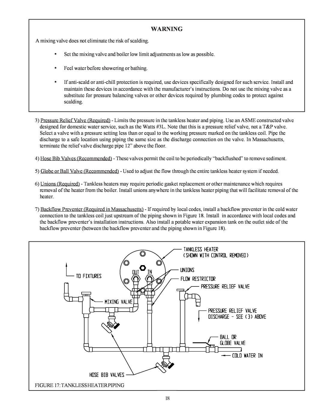
3)Pressure Relief Valve (Required) - Limits the pressure in the tankless heater and piping. Use an ASME constructed valve designed for domestic water service, such as the Watts #3L. Note that this is a pressure relief valve, not a T&P valve. Select a valve with a pressure setting less than or equal to the working pressure marked on the tankless coil. Pipe the discharge to a safe location using piping the same size as the discharge connection on the valve. In Massachusetts, terminate the relief valve discharge pipe 12” above the floor.
4)Hose Bib Valves (Recommended) - These valves permit the coil to be periodically “backflushed” to remove sediment.
5)Globe or Ball Valve (Recommended) - Used to adjust the flow through the entire tankless heater system if needed.
6)Unions (Required) - Tankless heaters may require periodic gasket replacement or other maintenance which requires removal of the heater from the boiler. Install unions anywhere in the tankless heater piping that will facilitate removal of the heater.
7)Backflow Preventer (Required in Massachusetts) - If required by local codes, install a backflow preventer in the cold water connection to the tankless coil just upstream of the piping shown in Figure 18. Install in accordance with local codes and the backflow preventer’s installation instructions. Also install a potable water expansion tank on the outlet side of the backflow preventer (between the backflow preventer and the piping shown in Figure 18).
FIGURE 17:TANKLESSHEATERPIPING
19
18