VII Gas Piping
Gas piping to the boiler must be sized to deliver adequate gas for the boiler to fire at the nameplate input at a line pressure between the minimum and maximum values shown on the rating plate. For more information on gas line sizing, consult the utility or Chapter 2 of the National Fuel Gas Code.
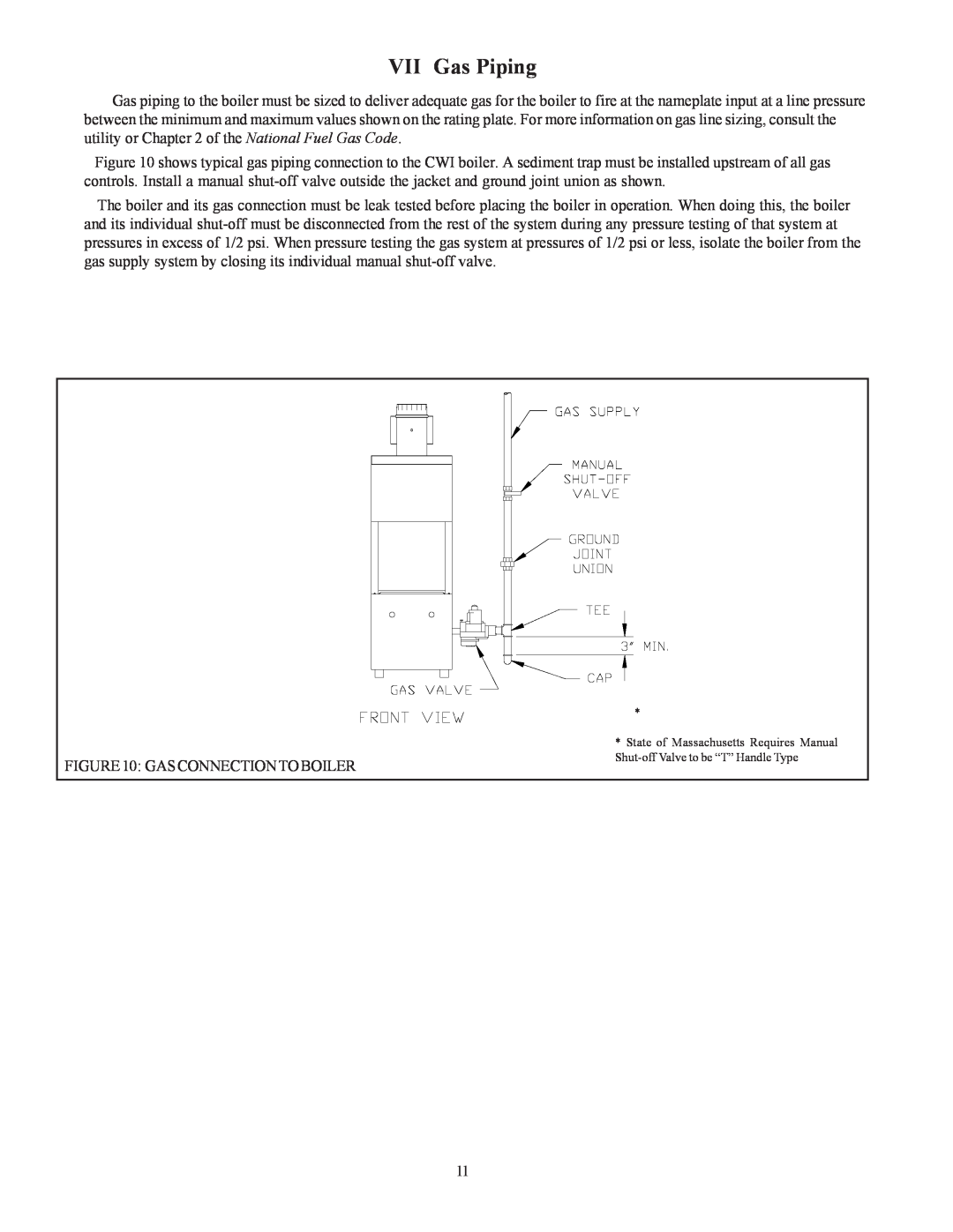
Figure 10 shows typical gas piping connection to the CWI boiler. A sediment trap must be installed upstream of all gas controls. Install a manual
The boiler and its gas connection must be leak tested before placing the boiler in operation. When doing this, the boiler and its individual
FIGURE10: GASCONNECTIONTOBOILER
*
*State of Massachusetts Requires Manual
12
11
