CPS725SL
Guaranteed Uninterruptible Power System
7.Disconnect the battery wires from the battery.
8.Install the replacement battery by connecting the red wire to the positive (+) terminal of the battery and connecting the black wire to the negative
9.Slide the battery back into the compartment.
10.Replace the outlet cover and the 6 retaining screws.
11.Recharge the unit for 4 – 8 hours to ensure the UPS performs expected runtime.
REMINDER: Batteries are consider HAZARDOUS WASTE and must be disposed of properly. Contact your local government for more information about proper disposal and recycling of batteries.
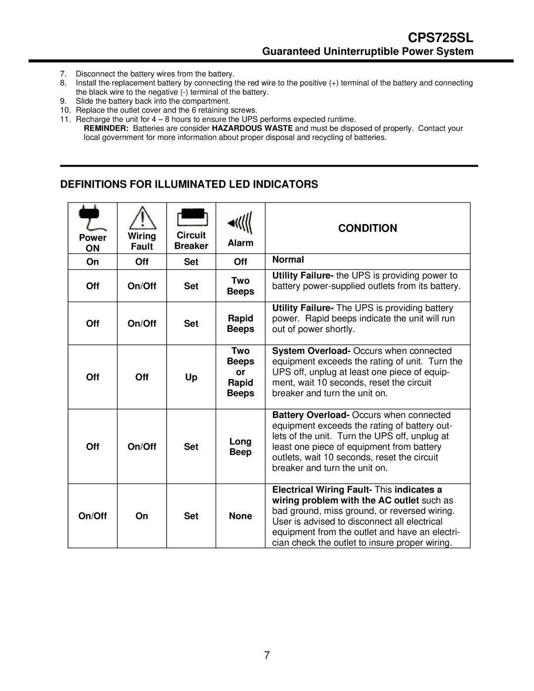
DEFINITIONS FOR ILLUMINATED LED INDICATORS
Power | Wiring | Circuit |
| CONDITION | |
Alarm |
| ||||
ON | Fault | Breaker |
| ||
On | Off | Set | Off | Normal | |
Off | On/Off | Set | Two | Utility Failure- the UPS is providing power to | |
battery | |||||
Beeps | |||||
|
|
|
| ||
|
|
|
|
| |
|
|
| Rapid | Utility Failure- The UPS is providing battery | |
Off | On/Off | Set | power. Rapid beeps indicate the unit will run | ||
Beeps | out of power shortly. | ||||
|
|
| |||
|
|
|
|
| |
|
|
| Two | System Overload- Occurs when connected | |
|
|
| Beeps | equipment exceeds the rating of unit. Turn the | |
Off | Off | Up | or | UPS off, unplug at least one piece of equip- | |
Rapid | ment, wait 10 seconds, reset the circuit | ||||
|
|
| |||
|
|
| Beeps | breaker and turn the unit on. | |
|
|
|
|
| |
|
|
|
| Battery Overload- Occurs when connected | |
|
|
|
| equipment exceeds the rating of battery out- | |
Off | On/Off | Set | Long | lets of the unit. Turn the UPS off, unplug at | |
least one piece of equipment from battery | |||||
Beep | |||||
|
|
| outlets, wait 10 seconds, reset the circuit | ||
|
|
|
| ||
|
|
|
| breaker and turn the unit on. | |
|
|
|
|
| |
|
|
|
| Electrical Wiring Fault- This indicates a | |
|
|
|
| wiring problem with the AC outlet such as | |
On/Off | On | Set | None | bad ground, miss ground, or reversed wiring. | |
User is advised to disconnect all electrical | |||||
|
|
|
| ||
|
|
|
| equipment from the outlet and have an electri- | |
|
|
|
| cian check the outlet to insure proper wiring. |
7
