Chapter 2: Installation
HDD LED
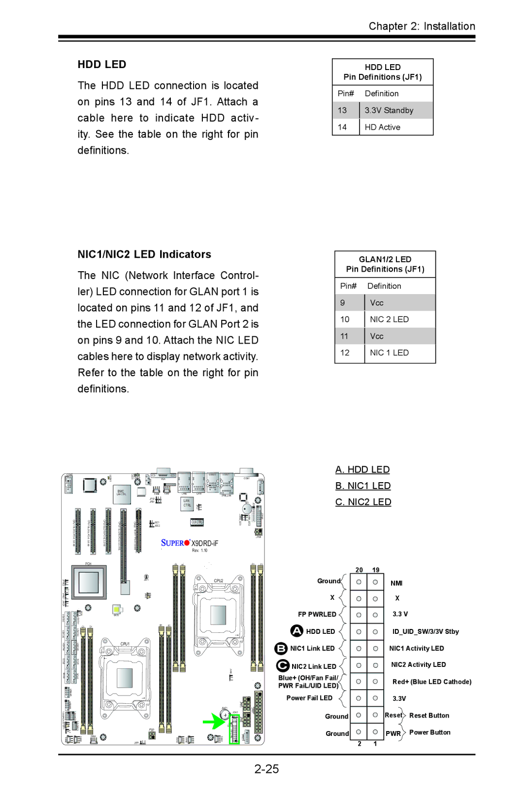
The HDD LED connection is located on pins 13 and 14 of JF1. Attach a cable here to indicate HDD activ- ity. See the table on the right for pin definitions.
NIC1/NIC2 LED Indicators
The NIC (Network Interface Control- ler) LED connection for GLAN port 1 is located on pins 11 and 12 of JF1, and the LED connection for GLAN Port 2 is on pins 9 and 10. Attach the NIC LED cables here to display network activity. Refer to the table on the right for pin definitions.
HDD LED
Pin Definitions (JF1)
Pin# Definition
133.3V Standby
14HD Active
GLAN1/2 LED
Pin Definitions (JF1)
Pin# Definition
9Vcc
10NIC 2 LED
11Vcc
12NIC 1 LED
| 1 |
COM2 | LEDM |
| |
| BMC CTRL |
CPU1 SLOT3 | CPU1 SLOT4 | CPU1 SLOT5 |
3.0 | 3.0 | 3.0 |
X8 | X8 | X8 |
BMC
LAN CTRL
6 CPU2 SLOT6
LED3 | JIPMB1 |
|
| USB2/3 | USB0/1 |
|
|
|
JUIDB |
| VGA |
|
|
| COM1 |
| USB6 |
|
|
|
|
|
| |||
| FAN8 | FAN7 | LAN2 | LAN1 | IPMI_LAN |
|
|
|
| JPG1 |
|
|
|
|
|
| |
|
| LAN |
|
|
| 1 |
| |
| JPB1 |
|
|
| SP1 |
|
| |
|
|
| CTRL | JPL1 | 1 | JD 2 | 1 | |
CPU2 | JI2C2 |
|
| CLK CTRL | JVRM I2C | JVRM I2C |
| JTPM |
| JI2C1 |
|
|
|
|
|
| |
SLOT7 |
| JPW4 | |
| |||
| |||
X8 | Rev. 1.10 |
|
A. HDD LED B. NIC1 LED C. NIC2 LED
|
|
| PCH |
2 |
|
|
|
JPME |
|
|
|
1 |
|
|
|
JPME |
|
|
|
JWD1 |
|
|
|
JSD1 A1ATI |
| ||
|
|
| |
A2ATI- | C1 | D1 | |
|
| ||
S |
|
|
|
|
| ||
SCU0 | SCU1 |
|
|
SCU2 | SCU3 |
|
|
| USB4/5 |
|
|
BIOS
CPU1
G1 H1
JBT1
JRK1![]()
B1 A1
F1 | E1 |
CPU2 |
|
JVR2
Ground![]()
X
FP PWRLED
AHDD LED ![]()
BNIC1 Link LED
C NIC2 Link LED
Blue+ (OH/Fan Fail/
PWR FaiL/UID LED)
Power Fail LED
20 | 19 |
NMI
X
3.3 V
ID_UID_SW/3/3V Stby
NIC1 Activity LED
NIC2 Activity LED
Red+ (Blue LED Cathode)
3.3V
| USB8/9 |
|
|
|
| ||
JSTBY1 | 1 JL |
| |
FAN6 |
| FAN5 | FAN4 |
|
|
|
|
| JBAT1 |
| JPW3 | |
|
|
|
| JPW1 | ||
|
|
|
| +JOH1 | ||
|
|
|
|
|
| JPW2 |
|
|
|
| LED2 |
|
|
| JPW5 |
|
| FP |
|
|
JVR1 | FAN3 | FAN2 | FAN1 | CTRL | 1 JF | JPI2C1 |
Ground
Ground
2 1
Reset Reset Button
PWR Power Button