

X9DRD-iF/LF Motherboard User’s Manual
Universal Serial Bus (USB)
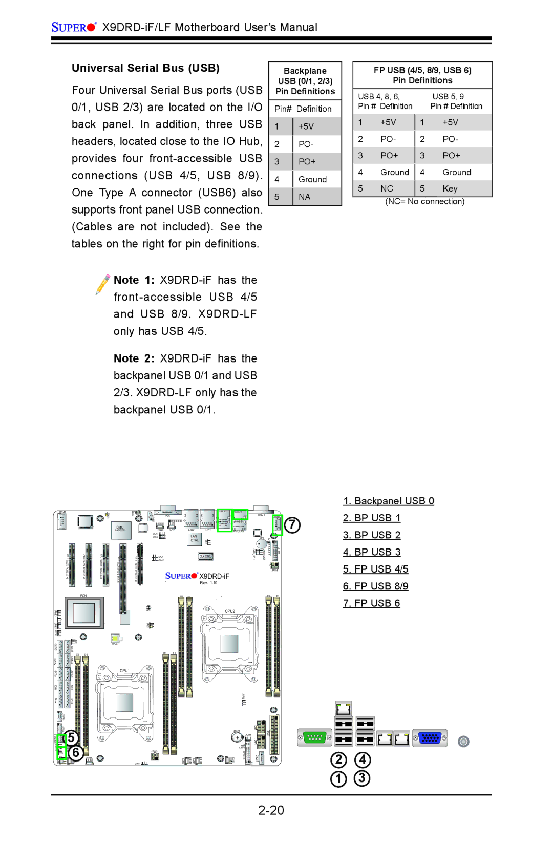
Four Universal Serial Bus ports (USB 0/1, USB 2/3) are located on the I/O back panel. In addition, three USB headers, located close to the IO Hub, provides four
Note 1:
Note 2:
Backplane
USB (0/1, 2/3)
Pin Definitions
Pin# Definition
1+5V
2PO-
3PO+
4Ground
5NA
FP USB (4/5, 8/9, USB 6)
Pin Definitions
USB 4, 8, 6, |
| USB 5, 9 | |
Pin # Definition |
| Pin # Definition | |
1 | +5V |
| +5V |
1 | |||
2 | PO- |
| PO- |
2 | |||
3 | PO+ |
| PO+ |
3 | |||
4 | Ground |
| Ground |
4 | |||
5 | NC |
| Key |
5 | |||
|
|
| |
| (NC= No connection) | ||
COM2
BMC CTRL
CPU1 SLOT3 |
| CPU1 SLOT4 |
3.0 |
| 3.0 |
X8 |
| X8 |
|
| PCH |
2 |
|
|
JPME |
|
|
1 |
|
|
JPME |
|
|
JWD1 |
|
|
A0AT | A1 | JSD1 |
| 1 |
| LEDM |
| BMC |
| LAN CTRL |
| 6 |
CPU1 SLOT5 | CPU2 SLOT6PCI |
3.0 X8 |
LED3 | JIPMB1 |
|
| USB2/3 | USB0/1 |
|
|
|
|
JUIDB |
| VGA |
|
|
| COM1 |
| USB6 |
|
| FAN8 | FAN7 | LAN2 | LAN1 | IPMI_LAN |
|
|
| 7 |
| JPG1 |
| LAN |
|
|
| 1 |
|
|
| JPB1 |
|
|
| SP1 | JD |
|
| |
|
|
| CTRL | JPL1 | 1 | 2 | 1 |
| |
CPU2 | JI2C2 |
|
| CLK CTRL | JVRM I2C | JVRM I2C |
| JTPM |
|
| JI2C1 |
|
|
|
|
|
|
| |
SLOT7 |
|
|
|
|
|
|
| JPW4 |
|
|
|
|
|
|
|
| |||
|
|
|
|
|
|
|
| ||
|
|
|
| Rev. 1.10 |
|
|
|
|
|
G1 | H1 | F1 | E1 |
JBT1 | CPU2 |
JRK1![]()
1.Backpanel USB 0
2.BP USB 1
3.BP USB 2
4.BP USB 3
5.FP USB 4/5
6.FP USB 8/9
7.FP USB 6
| ATI |
|
| |
|
|
|
| |
A2ATI- |
| C1 | D1 | |
|
|
| ||
S |
|
|
|
|
|
|
| ||
SCU0 |
| SCU1 |
|
|
SCU2 |
| SCU3 |
|
|
| USB4/5 |
|
|
|
USB8/9 | 5- |
|
| |
JSTBY1 | 1 | 6 FAN4 | ||
| JL | |||
FAN6 |
| |||
| N5 |
| ||
BIOS
B1 A1
CPU1
JPW5
JVR1 ![]()
FAN3 | FAN2 |
JVR2
JBAT1 | JPW3 | |
JPW1 | ||
JOH1 | ||
| JPW2 | |
LED2 |
|
FAN1 | FP CTRL | JPI2C1 1 JF | 2 | 4 |
|
|
| 1 | 3 |
