X9DRD-iF/LF Motherboard User’s Manual
Front Control Panel Pin Definitions
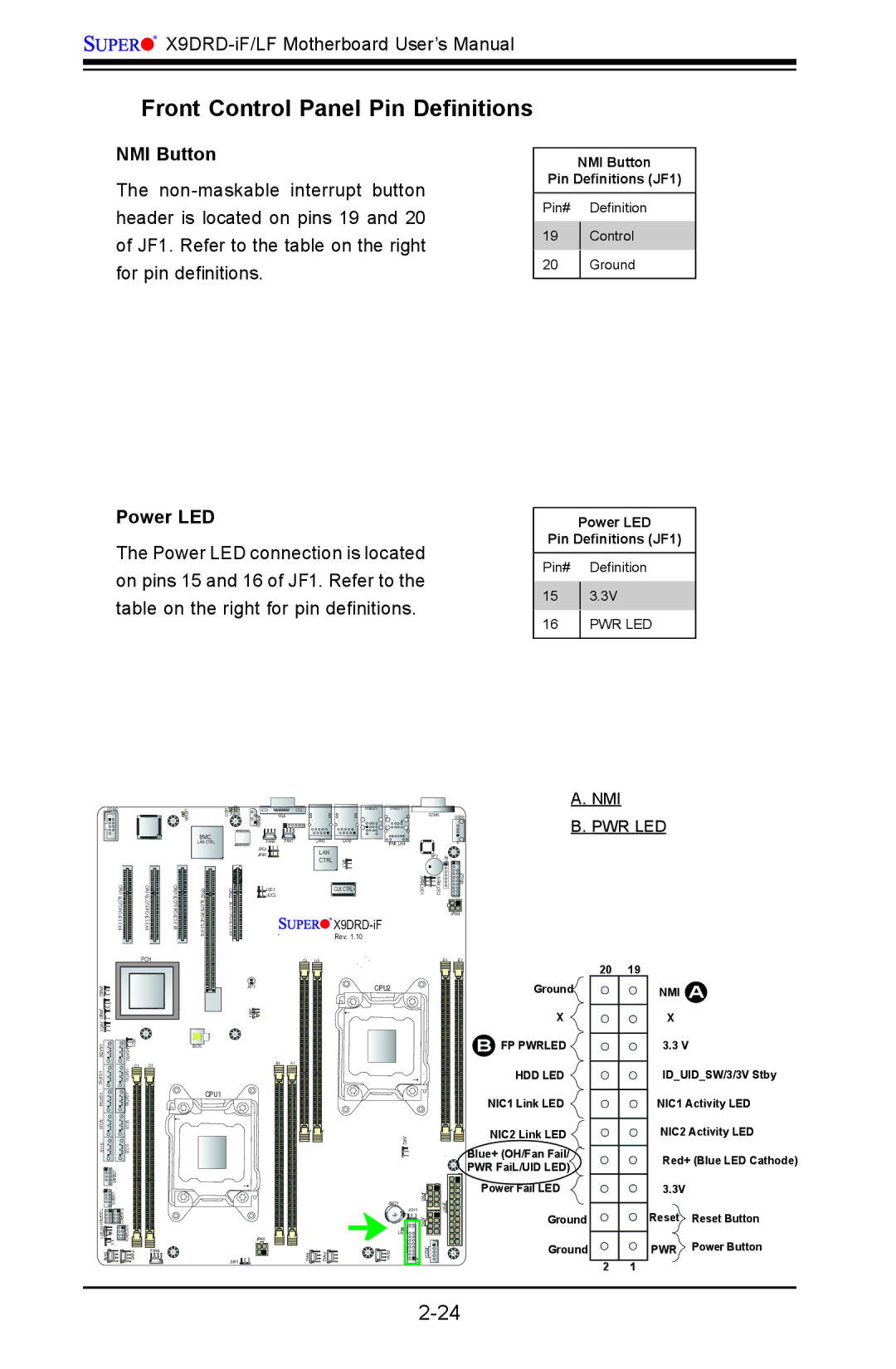
NMI Button
The
Power LED
The Power LED connection is located on pins 15 and 16 of JF1. Refer to the table on the right for pin definitions.
1
NMI Button
Pin Definitions (JF1)
Pin# Definition
19Control
20Ground
Power LED
Pin Definitions (JF1)
Pin# Definition
153.3V
16PWR LED
A. NMI
COM2 | LEDM |
| |
| BMC CTRL |
CPU1 SLOT3 | CPU1 SLOT4 | CPU1 SLOT5 |
3.0 | 3.0 | 3.0 |
X8 | X8 | X8 |
BMC
LAN CTRL
6 CPU2 SLOT6 ![]()
![]()
![]()
![]()
LED3 | JIPMB1 |
|
| USB2/3 | USB0/1 |
|
|
|
|
JUIDB |
| VGA |
|
|
| COM1 |
| USB6 | B. PWR LED |
|
|
|
|
|
| ||||
|
|
|
|
|
|
|
|
| |
| FAN8 FAN7 | LAN2 | LAN1 | IPMI_LAN |
|
|
|
| |
| JPG1 |
|
|
|
|
|
|
| |
|
| LAN |
|
|
| 1 |
|
| |
| JPB1 |
|
|
| SP1 |
|
|
| |
|
|
| CTRL | JPL1 | 1 | JD 2 | 1 |
| |
CPU2 | JI2C2 |
|
| CLK CTRL | JVRM I2C | JVRM I2C |
| JTPM |
|
| JI2C1 |
|
|
|
|
|
|
| |
SLOT7 |
| JPW4 | |
| |||
| |||
| Rev. 1.10 |
|
|
|
|
| PCH |
2 |
|
|
|
|
JPME |
|
|
|
|
1 |
|
|
|
|
JPME |
|
|
|
|
JWD1 |
|
|
|
|
| JSD1 A1ATI |
| ||
|
|
|
| |
A2ATI- |
| C1 | D1 | |
|
|
| ||
S |
|
|
|
|
|
|
| ||
SCU0 |
| SCU1 |
|
|
SCU2 |
| SCU3 |
|
|
| USB4/5 |
|
|
|
| USB8/9 |
|
|
|
|
|
| ||
JSTBY1 | 1 JL |
|
| |
FAN6 |
|
| FAN5 | FAN4 |
|
|
| ||
BIOS
CPU1
JBT1
JRK1![]()
JPW5
JVR1 ![]()
| G1 | H1 |
| F1 | E1 |
|
| CPU2 |
|
| Ground |
|
|
|
|
| X |
|
|
|
|
| B FP PWRLED |
B1 | A1 |
|
|
|
|
|
|
|
|
| HDD LED |
|
|
|
|
| NIC1 Link LED |
|
| JVR2 |
|
| NIC2 Link LED |
|
|
|
|
| Blue+ (OH/Fan Fail/ |
|
|
|
|
| PWR FaiL/UID LED) |
|
|
| JPW3 |
| Power Fail LED |
|
| JBAT1 | JPW1 |
| |
|
|
|
| ||
|
| + | JOH1 | Ground | |
|
| JPW2 |
| ||
|
| LED2 |
|
|
|
|
|
| FP |
| Ground | |
FAN3 | FAN2 | FAN1 | CTRL | JPI2C1 1 JF | ||
|
20 | 19 |
2 1
NMI A
X
3.3 V
ID_UID_SW/3/3V Stby
NIC1 Activity LED
NIC2 Activity LED
Red+ (Blue LED Cathode)
3.3V
Reset Reset Button
PWR Power Button