X9DRD-iF/LF Motherboard User’s Manual
Unit Identifier Switch/UID LED Indicators
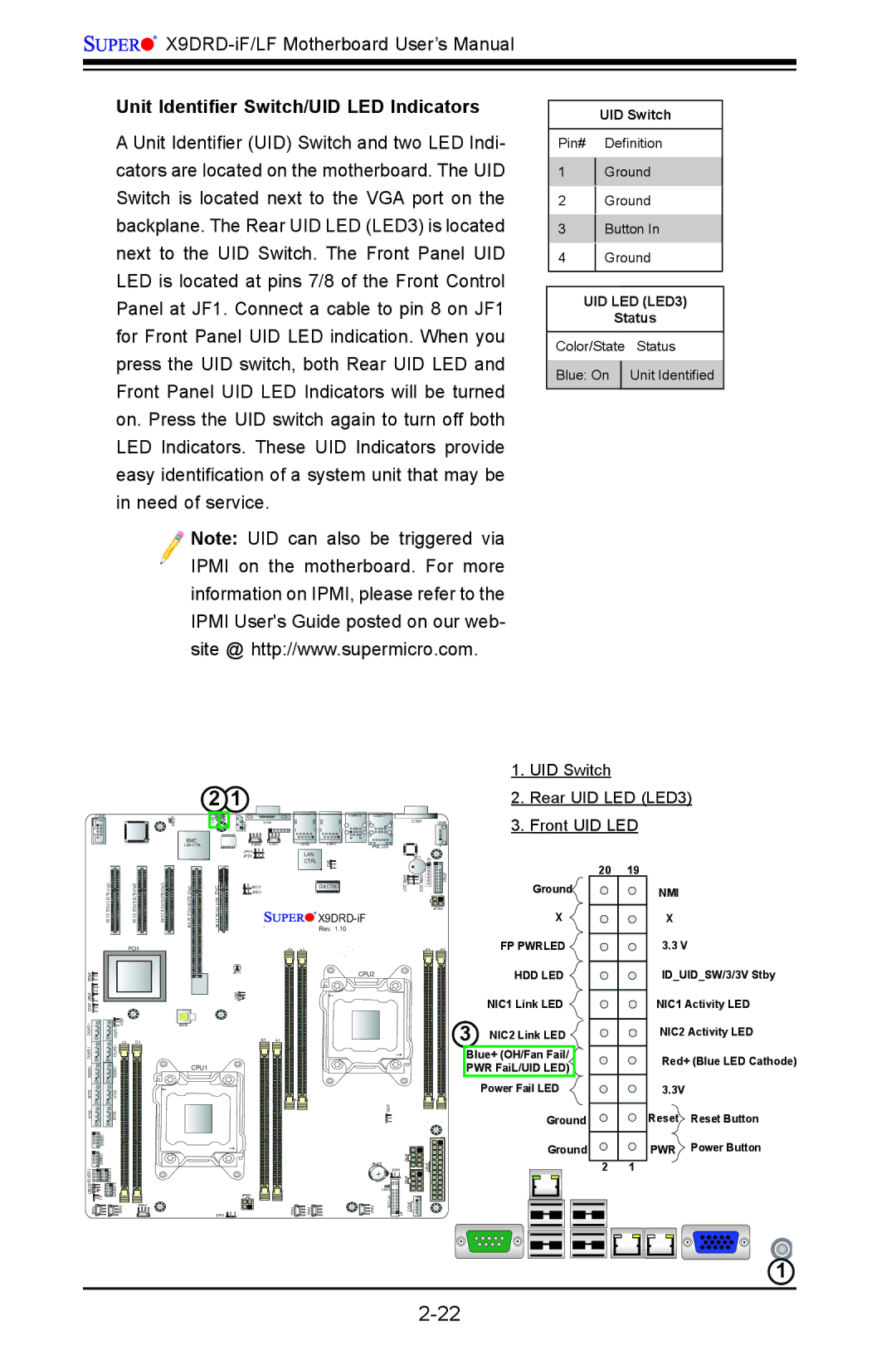
A Unit Identifier (UID) Switch and two LED Indi- cators are located on the motherboard. The UID Switch is located next to the VGA port on the backplane. The Rear UID LED (LED3) is located next to the UID Switch. The Front Panel UID LED is located at pins 7/8 of the Front Control Panel at JF1. Connect a cable to pin 8 on JF1 for Front Panel UID LED indication. When you press the UID switch, both Rear UID LED and Front Panel UID LED Indicators will be turned on. Press the UID switch again to turn off both LED Indicators. These UID Indicators provide easy identification of a system unit that may be in need of service.
Note: UID can also be triggered via IPMI on the motherboard. For more information on IPMI, please refer to the IPMI User's Guide posted on our web- site @ http://www.supermicro.com.
UID Switch
Pin# Definition
1Ground
2Ground
3Button In
4Ground
UID LED (LED3)
Status
Color/State Status
Blue: On | Unit Identified |
|
|
2 1
1
COM2 | LEDM | LED3 | JIPMB1 |
|
BMC CTRL | VGA | |||
|
| JUIDB |
|
BMC | FAN8 FAN7 |
LAN CTRL |
JPG1 ![]()
![]()
![]()
JPB1 ![]()
|
|
|
| 1. | UID Switch |
|
|
|
| 2. | Rear UID LED (LED3) |
|
| USB2/3 USB0/1 |
| 3. | Front UID LED |
|
| COM1 | USB6 | ||
LAN2 | LAN1 | IPMI_LAN |
|
|
|
|
|
|
|
|
LAN |
| 1 |
CTRL | 1 | SP12 JD |
CPU1 SLOT3 | CPU1 SLOT4 | CPU1 SLOT5 |
6 CPU2 SLOT6
CPU2 SLOT7
![]() JI2C1
JI2C1 ![]() JI2C2
JI2C2
JPL1 |
|
| 1 |
CLK CTRL | JVRM I2C | JVRM I2C | JTPM |
Ground![]()
20 | 19 |
| NMI |
3.0 | 3.0 | 3.0 |
X8 | X8 | X8 |
![]()
![]()
![]()
Rev. 1.10
JPW4
X
X |
| PCH |
2 |
|
JPME |
|
1 |
|
JPME |
|
JWD1 |
|
A0AT | JSD1 A1 |
JBT1
JRK1![]()
G1 | H1 | F1 | E1 |
CPU2 |
FP PWRLED HDD LED ![]()
NIC1 Link LED
3.3 V |
ID_UID_SW/3/3V Stby |
NIC1 Activity LED |
ATI |
|
| |
|
|
| |
A2ATI- | C1 | D1 | |
|
| ||
S |
|
|
|
|
| ||
SCU0 | SCU1 |
|
|
SCU2 | SCU3 |
|
|
BIOS
B1 A1
CPU1
JVR2
3 NIC2 Link LED
Blue+ (OH/Fan Fail/ PWR FaiL/UID LED)
Power Fail LED
Ground
NIC2 Activity LED |
Red+ (Blue LED Cathode) |
3.3V |
Reset Reset Button |
| USB4/5 |
|
|
| USB8/9 |
|
|
|
| ||
JSTBY1 | 1 JL |
| |
FAN6 |
| FAN5 | FAN4 |
|
|
JPW5
JVR1 ![]()
|
|
|
|
| JPW3 | Ground | 2 | PWR | Power Button |
|
|
| JOH1 | JPW1 | 1 |
| |||
|
| JBAT1 |
|
|
|
|
|
| |
|
|
|
|
| JPW2 |
|
|
|
|
|
|
| LED2 |
|
|
|
|
|
|
FAN3 | FAN2 | FAN1 | FP CTRL | 1 JF | JPI2C1 |
|
|
|
|
1