X9DRD-iF/LF Motherboard User’s Manual
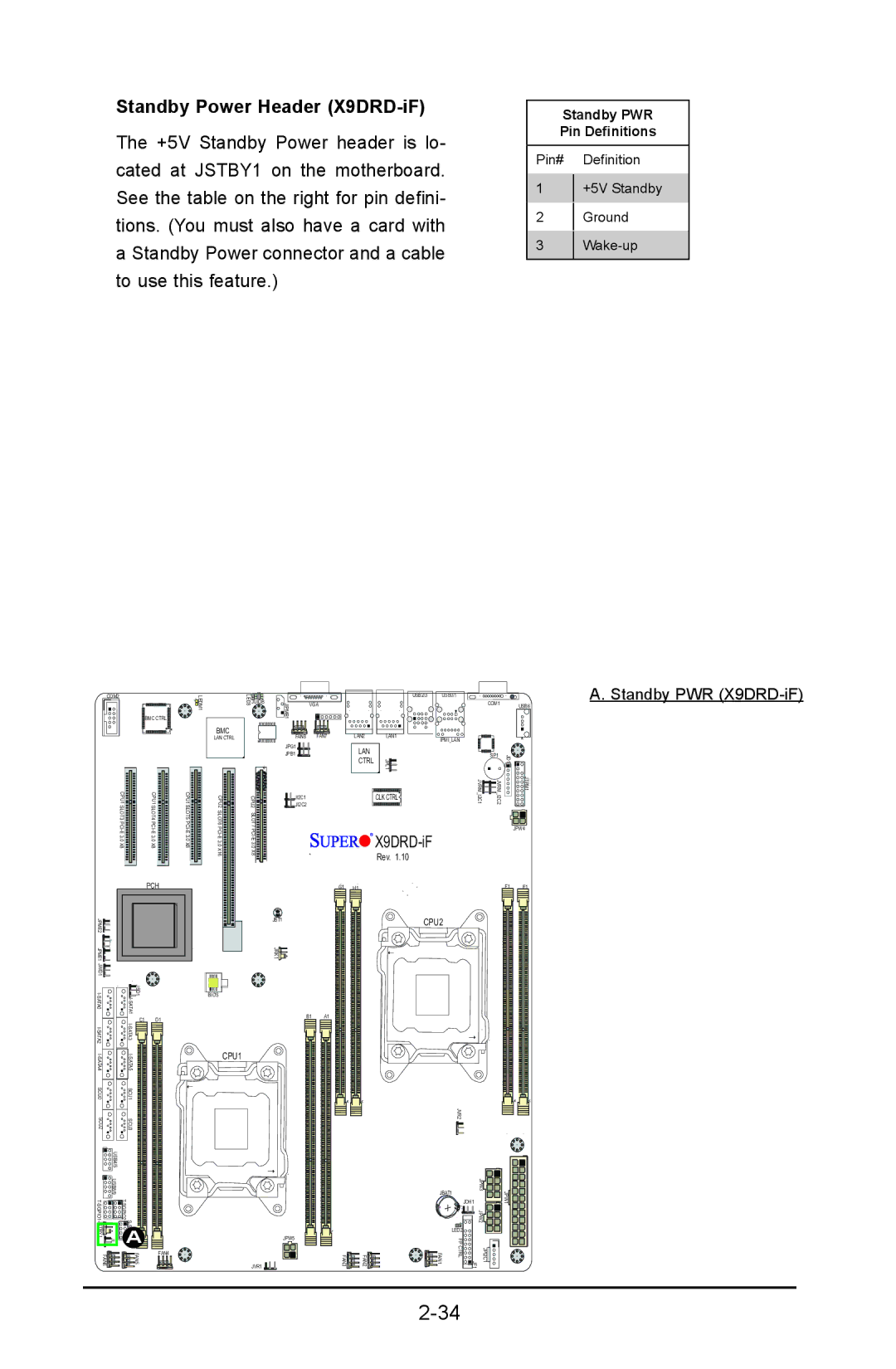
Standby Power Header (X9DRD-iF)
The +5V Standby Power header is lo- cated at JSTBY1 on the motherboard. See the table on the right for pin defini- tions. (You must also have a card with a Standby Power connector and a cable to use this feature.)
Standby PWR
Pin Definitions
Pin# Definition
1+5V Standby
2Ground
3Wake-up
COM2
BMC CTRL
CPU1SLOT3 | CPU1SLOT4 |
| 1 |
| LEDM |
| BMC |
| LAN CTRL |
| 6 |
CPU1SLOT5 | CPU2 |
LED3JUIDB
CPU2![]()
![]()
![]()
![]()
![]()
|
|
| USB2/3 | USB0/1 |
|
|
|
JIPMB1 | VGA |
|
|
| COM1 |
| USB6 |
|
|
|
|
|
|
| |
FAN8 | FAN7 | LAN2 | LAN1 | IPMI_LAN |
|
|
|
JPG1 |
|
|
|
|
|
| |
| LAN |
|
|
| 1 |
| |
JPB1 |
|
|
| SP1 |
|
| |
|
| CTRL | JPL1 | 1 | JD 2 | 1 | |
|
|
| |||||
JI2C1 |
|
| CLK CTRL | JVRM I2C | JVRM I2C |
| JTPM |
JI2C2 |
|
|
|
|
|
|
|
A. Standby PWR
3.0 | 3.0 |
X8 | X8 |
SLOT6 PCI | |
3.0 X8 |
SLOT7


X9DRD-iF
Rev. 1.10
JPW4
|
|
| PCH |
2 |
|
|
|
JPME |
|
|
|
1 |
|
|
|
JPME |
|
|
|
JWD1 |
|
|
|
JSD1 A1ATI |
| ||
|
|
| |
A2ATI- | C1 | D1 | |
|
| ||
S |
|
|
|
|
| ||
SCU0 | SCU1 |
|
|
SCU2 | SCU3 |
|
|
| USB4/5 |
|
|
| G1 | H1 |
JBT1 |
|
|
JRK1 |
|
|
BIOS |
|
|
B1 | A1 |
|
CPU1 |
|
|
F1 | E1 |
CPU2 |
|
JVR2
| USB8/9 |
|
|
|
| ||
JSTBY1 | 1 JL | FAN4 | |
FAN6 |
| FAN5 | |
|
|
JBAT1 | JPW3 | |
JPW1 | ||
JOH1 |
+ |
JPW2 |
LED2 |
| JPW5 |
|
| FP CTRL |
|
JVR1 | FAN3 | FAN2 | FAN1 | JPI2C1 1 JF | |
|
|
|
|
|