X9DRD-iF/LF Motherboard User’s Manual
2-6 Control Panel Connectors and I/O Ports
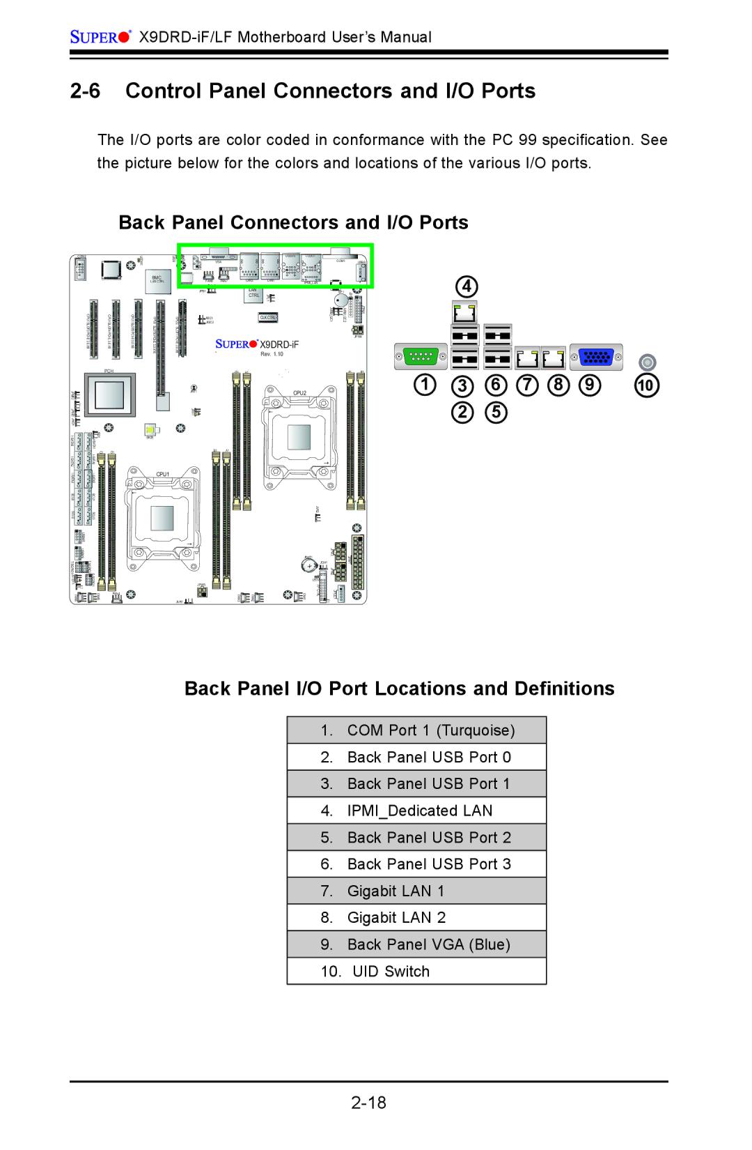
The I/O ports are color coded in conformance with the PC 99 specification. See the picture below for the colors and locations of the various I/O ports.
Back Panel Connectors and I/O Ports
| 1 |
COM2 | LEDM |
| |
| BMC CTRL |
| CPU1 SLOT3 |
|
| CPU1 SLOT4 | CPU1 SLOT5 |
| 3.0 |
|
| 3.0 | 3.0 |
| X8 |
|
| X8 | X8 |
|
|
|
| PCH |
|
2 |
|
|
|
|
|
JPME |
|
|
|
|
|
1 |
|
|
|
|
|
JPME |
|
|
|
|
|
JWD1 |
|
|
|
|
|
| A1ATI | JSD1 |
|
| |
|
|
|
|
| |
A2ATI- |
| C1 | D1 |
| |
|
|
|
| ||
S |
|
|
|
|
|
|
|
|
| ||
SCU0 |
| SCU1 |
|
|
|
SCU2 |
| SCU3 |
|
|
|
| USB4/5 |
|
|
|
|
| USB8/9 |
|
|
|
|
|
|
| |||
JSTBY1 | 1 JL |
|
|
| |
FAN6 |
|
| FAN5 | FAN4 |
|
|
|
|
|
BMC
LAN CTRL
6 CPU2 SLOT6
BIOS
CPU1
LED3 | JIPMB1 |
|
| USB2/3 | USB0/1 |
|
|
|
JUIDB |
| VGA |
|
|
| COM1 |
| USB6 |
|
|
|
|
|
| |||
| FAN8 | FAN7 | LAN2 | LAN1 | IPMI_LAN |
|
|
|
| JPG1 |
| LAN |
|
|
| 1 |
|
| JPB1 |
|
|
| SP1 | JD |
| |
|
|
| CTRL | JPL1 | 1 | 2 | 1 | |
CPU2 | JI2C2 |
|
| CLK CTRL | JVRM I2C | JVRM I2C |
| JTPM |
| JI2C1 |
|
|
|
|
|
| |
SLOT7 |
|
|
|
|
|
|
| JPW4 |
|
|
|
|
|
| |||
|
|
|
|
|
|
| ||
|
|
|
| Rev. 1.10 |
|
|
|
|
G1 | H1 | F1 | E1 |
JBT1 | CPU2 |
JRK1![]()
B1 A1
JVR2
JBAT1 | JPW3 | |
JPW1 | ||
JOH1 |
JPW2 |
LED2 |
| JPW5 |
|
| FP |
|
JVR1 | FAN3 | FAN2 | FAN1 | CTRL | JPI2C1 1 JF |
|
|
|
|
|
4
1 | 3 | 6 | 7 | 8 | 9 | 10 |
| 2 | 5 |
|
|
|
|
Back Panel I/O Port Locations and Definitions
1.COM Port 1 (Turquoise)
2.Back Panel USB Port 0
3.Back Panel USB Port 1
4.IPMI_Dedicated LAN
5.Back Panel USB Port 2
6.Back Panel USB Port 3
7.Gigabit LAN 1
8.Gigabit LAN 2
9.Back Panel VGA (Blue)
10.UID Switch