X9DRD-iF/LF Motherboard User’s Manual
2-7 Connecting Cables
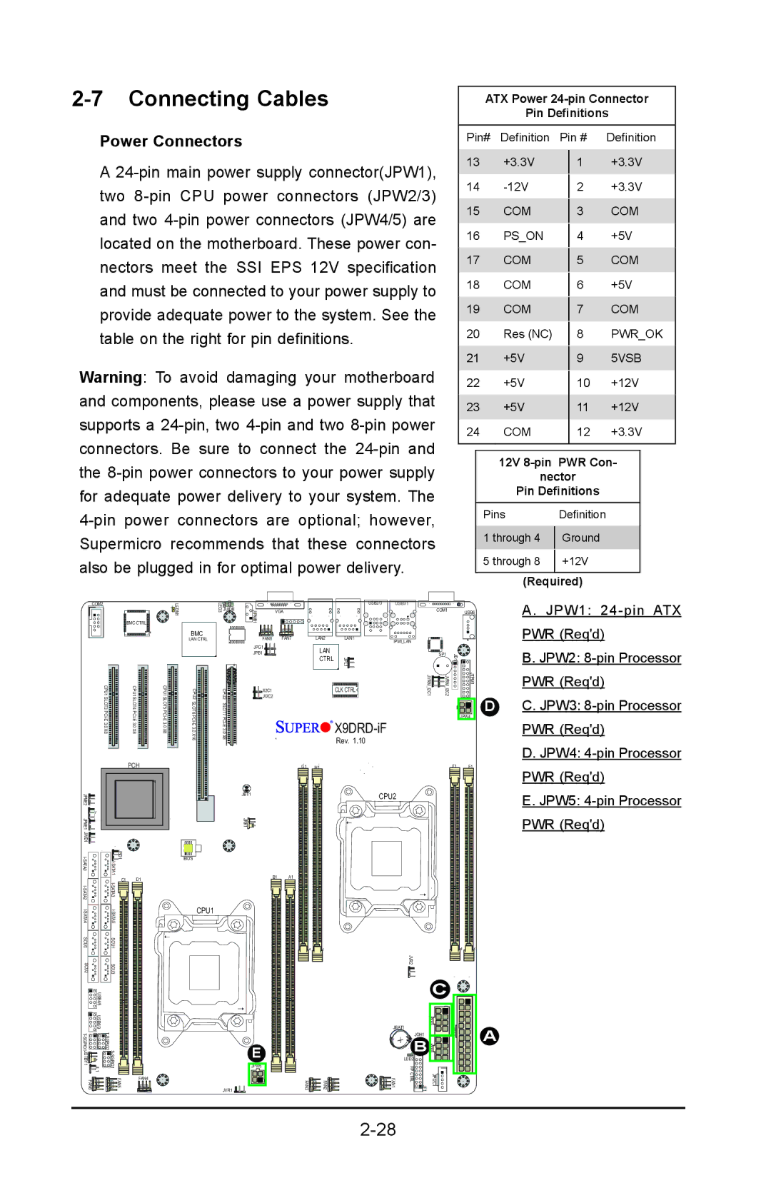
Power Connectors
A
Warning: To avoid damaging your motherboard and components, please use a power supply that supports a
ATX Power 24-pin Connector
Pin Definitions
Pin# | Definition |
| Pin # | Definition | |||
13 | +3.3V |
|
| +3.3V | |||
|
| 1 | |||||
14 |
|
|
| +3.3V | |||
|
| 2 | |||||
15 | COM |
|
|
| COM | ||
|
| 3 | |||||
16 | PS_ON |
|
|
| +5V | ||
|
| 4 | |||||
17 | COM |
|
|
| COM | ||
|
| 5 | |||||
18 | COM |
|
|
| +5V | ||
|
| 6 | |||||
19 | COM |
|
|
| COM | ||
|
| 7 | |||||
20 | Res (NC) |
|
|
| PWR_OK | ||
|
| 8 | |||||
21 | +5V |
|
|
| 5VSB | ||
|
| 9 | |||||
22 | +5V |
|
|
| +12V | ||
|
| 10 | |||||
23 | +5V |
|
| 11 | +12V | ||
24 | COM |
|
| 12 | +3.3V | ||
|
|
|
|
|
| ||
|
|
|
| ||||
|
| 12V |
| ||||
|
| nector |
|
| |||
|
| Pin Definitions |
|
| |||
| Pins |
| Definition |
|
| ||
| 1 through 4 |
| Ground |
|
| ||
|
|
|
| ||||
| 5 through 8 |
| +12V |
|
| ||
|
|
|
| ||||
|
|
|
|
|
|
|
|
(Required)
|
|
|
|
|
| 1 |
|
|
|
|
|
|
|
|
|
|
|
|
|
|
|
| COM2 |
|
|
|
| LEDM | LED3 |
|
|
|
|
| USB2/3 | USB0/1 |
|
|
| COM1 |
|
| A. JPW1: |
|
|
|
|
|
| JIPMB1 |
|
|
|
|
|
|
|
|
|
|
| ||||
|
|
|
|
|
|
| JUIDB |
| VGA |
|
|
|
|
|
|
|
| USB6 |
| ||
|
|
|
|
|
|
|
|
|
|
|
|
|
|
|
|
|
|
| |||
|
|
|
| BMC CTRL |
| LAN CTRL |
| FAN8 |
| FAN7 |
| LAN2 | LAN1 | IPMI_LAN |
|
|
|
|
| PWR (Req'd) | |
|
|
|
|
|
|
|
|
|
|
|
|
|
| ||||||||
|
|
|
|
|
| BMC |
|
|
|
|
|
|
|
|
|
|
|
|
|
|
|
|
|
|
|
|
|
|
| JPG1 |
|
|
| LAN |
|
|
|
|
|
| 1 JD |
| B. JPW2: |
|
|
|
|
|
| 6 |
| JPB1 |
|
|
| JPL1 |
|
| 1 | 2 | 1 | ||||
|
|
|
|
|
|
|
|
|
| CTRL |
|
| |||||||||
|
|
|
|
|
|
|
|
|
|
|
| SP1 |
|
|
| ||||||
|
|
|
|
|
|
|
|
|
|
| JVRM I2C | JVRM I2C |
| JTPM | PWR (Req'd) | ||||||
|
|
|
|
|
|
|
| JI2C1 |
|
|
|
| CLK CTRL |
|
|
|
|
|
|
| PWR (Req'd) |
|
|
|
|
|
|
|
| JI2C2 |
|
|
|
|
|
|
|
|
|
|
| D | C. JPW3: |
|
|
|
|
|
|
|
|
|
|
|
|
|
|
|
|
|
|
|
| JPW4 |
|
|
|
|
|
|
|
|
|
|
|
|
|
| Rev. 1.10 |
|
|
|
|
|
|
| D. JPW4: |
|
|
|
| PCH |
|
|
|
|
|
|
|
|
|
|
|
|
|
|
|
| |
|
|
|
|
|
|
|
|
|
| G1 | H1 |
|
|
|
|
|
| F1 | E1 | PWR (Req'd) | |
2 |
|
|
|
|
|
|
|
|
|
|
|
| CPU2 |
|
|
|
|
|
| ||
JPME |
|
|
|
|
|
|
| JBT1 |
|
|
|
|
|
|
|
|
|
| E. JPW5: | ||
1 |
|
|
|
|
|
|
|
|
|
|
|
|
|
|
|
|
|
|
|
| |
JPME |
|
|
|
|
|
|
| JRK1 |
|
|
|
|
|
|
|
|
|
|
|
| PWR (Req'd) |
JWD1 |
|
|
|
|
|
|
|
|
|
|
|
|
|
|
|
|
|
|
|
|
|
| JSD1 A1ATI |
|
| BIOS |
|
|
|
|
|
|
|
|
|
|
|
|
|
|
| ||
|
|
|
|
|
|
|
|
|
|
|
|
|
|
|
|
|
|
|
|
| |
A2ATI- |
| C1 | D1 |
|
|
|
| B1 | A1 |
|
|
|
|
|
|
|
|
|
|
| |
S |
|
|
|
|
|
|
|
|
|
|
|
|
|
|
|
|
|
|
|
|
|
|
|
|
| CPU1 |
|
|
|
|
|
|
|
|
|
|
|
|
|
|
| ||
|
|
|
|
|
|
|
|
|
|
|
|
|
|
|
|
|
|
|
| ||
SCU0 |
| SCU1 |
|
|
|
|
|
|
|
|
|
|
|
|
|
|
|
|
|
|
|
SCU2 |
| SCU3 |
|
|
|
|
|
|
|
|
|
|
|
| JVR2 |
|
|
|
|
|
|
| USB4/5 |
|
|
|
|
|
|
|
|
|
|
|
|
|
|
| C |
|
|
| |
|
|
|
|
|
|
|
|
|
|
|
|
|
|
|
|
|
|
|
|
| |
USB8/9 |
|
|
|
|
|
|
|
|
|
|
| JBAT1 | + |
| JPW3 |
| JPW1 | A |
| ||
|
|
|
|
|
|
|
|
|
|
|
|
|
|
| JOH1 |
|
|
|
| ||
JSTBY1 | 1JL |
|
|
|
|
| E |
|
|
|
|
|
| B | JPW2 |
|
|
|
| ||
|
|
|
|
|
|
|
|
|
|
| FP |
|
|
|
|
| |||||
|
|
|
|
|
|
|
|
|
|
|
|
| LED2 |
|
|
|
|
|
| ||
FAN6 |
| FAN5 |
|
|
|
| JPW5 |
|
| FAN3 | FAN2 |
| FAN1 | CTRL | 1JF | JPI2C1 |
|
|
| ||
| FAN4 |
|
|
|
|
|
|
|
|
|
| ||||||||||
|
|
|
|
|
|
| JVR1 |
|
|
|
|
|
|
|
|
|
|
|
|
|
|