HARDWARE
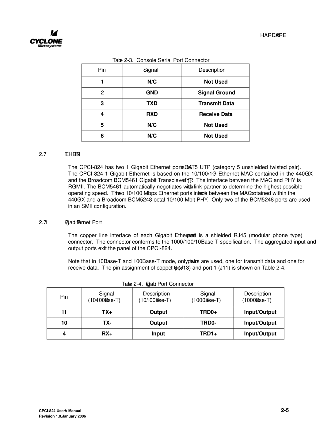
Table 2-3. Console Serial Port Connector
Pin | Signal | Description |
| | |
1 | N/C | Not Used |
| | |
2 | GND | Signal Ground |
| | |
3 | TXD | Transmit Data |
| | |
4 | RXD | Receive Data |
| | |
5 | N/C | Not Used |
| | |
6 | N/C | Not Used |
| | |
2.7ETHERNET
The CPCI-824 has two 1 Gigabit Ethernet ports for CAT5 UTP (category 5 unshielded twisted pair). The CPCI-824 1 Gigabit Ethernet is based on the 10/100/1G Ethernet MAC contained in the 440GX and the Broadcom BCM5461 Gigabit Transciever (PHY). The interface between the MAC and PHY is RGMII. The BCM5461 automatically negotiates with its link partner to determine the highest possible operating speed. The two 10/100 Mbps Ethernet ports interface between the MAC contained within the 440GX and a Broadcom BCM5248 octal 10/100 Mbit PHY. Only two of the BCM5248 ports are used in an SMII configuration.
2.7.1Gigabit Ethernet Port
The copper line interface of each Gigabit Ethernet port is a shielded RJ45 (modular phone type) connector. The connector conforms to the 1000/100/10Base-T specification. The aggregated input and output ports exit the panel of the CPCI-824.
Note that in 10Base-T and 100Base-T mode, only two pairs are used, one for transmit data and one for receive data. The pin assignment of copper port 0 (J13) and port 1 (J11) is shown on Table 2-4.
Table 2-4. Gigabit Port Connector
| Pin | Signal | Description | Signal | Description |
| (10/100Base-T) | (10/100Base-T) | (1000Base-T) | (1000Base-T) |
| |
| | | | | |
| 11 | TX+ | Output | TRD0+ | Input/Output |
| | | | | |
| 10 | TX- | Output | TRD0- | Input/Output |
| | | | | |
| 4 | RX+ | Input | TRD1+ | Input/Output |
| | | | | |
CPCI-824 User’s Manual | 2-5 |
Revision 1.0, January 2006 | |
