HARDWARE
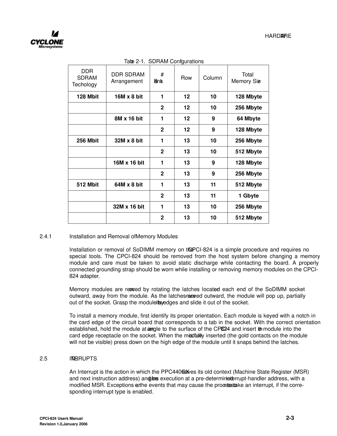
Table
DDR | DDR SDRAM | # |
|
| Total | |
SDRAM | Row | Column | ||||
Arrangement | Banks | Memory Size | ||||
Technology |
|
| ||||
|
|
|
|
| ||
|
|
|
|
|
| |
128 Mbit | 16M x 8 bit | 1 | 12 | 10 | 128 Mbyte | |
|
|
|
|
|
| |
|
| 2 | 12 | 10 | 256 Mbyte | |
|
|
|
|
|
| |
| 8M x 16 bit | 1 | 12 | 9 | 64 Mbyte | |
|
|
|
|
|
| |
|
| 2 | 12 | 9 | 128 Mbyte | |
|
|
|
|
|
| |
256 Mbit | 32M x 8 bit | 1 | 13 | 10 | 256 Mbyte | |
|
|
|
|
|
| |
|
| 2 | 13 | 10 | 512 Mbyte | |
|
|
|
|
|
| |
| 16M x 16 bit | 1 | 13 | 9 | 128 Mbyte | |
|
|
|
|
|
| |
|
| 2 | 13 | 9 | 256 Mbyte | |
|
|
|
|
|
| |
512 Mbit | 64M x 8 bit | 1 | 13 | 11 | 512 Mbyte | |
|
|
|
|
|
| |
|
| 2 | 13 | 11 | 1 Gbyte | |
|
|
|
|
|
| |
| 32M x 16 bit | 1 | 13 | 10 | 256 Mbyte | |
|
|
|
|
|
| |
|
| 2 | 13 | 10 | 512 Mbyte | |
|
|
|
|
|
|
2.4.1Installation and Removal of Memory Modules
Installation or removal of SoDIMM memory on the
Memory modules are removed by rotating the latches located on each end of the SoDIMM socket outward, away from the module. As the latches are moved outward, the module will pop up, partially out of the socket. Grasp the module by its edges and slide it out of the socket.
To install a memory module, first identify its proper orientation. Each module is keyed with a notch in the card edge of the circuit board that corresponds to a tab in the socket. With the correct orientation established, hold the module at an angle to the surface of the
2.5INTERRUPTS
An Interrupt is the action in which the PPC440GX saves its old context (Machine State Register (MSR) and next instruction address) and begins execution at a
Revision 1.0, January 2006 |
|
